Diffraction is interference produced when waves scatter from spatial structure. A periodic structure concentrates the scattered intensity at reciprocal-lattice conditions.
The spatial distribution of intensity produced by interference of a wave passing an aperture or obstacle. A circular aperture's far-field point-source pattern is an Airy disk; a Rayleigh criterion comparison superposes the intensities of two mutually incoherent sources.
Diffuse scattering generated by fluctuating lattice displacements. Resolved one-phonon creation and annihilation transfer both energy and crystal momentum, with Bose factors and . An energy-integrating diffraction measurement can record their summed intensity without resolving the small energy transfer. Phonon polarization, soft-mode frequencies and atomic scattering weights determine the pattern; static disorder supplies a distinct possible diffuse contribution.
Ewald sphere curvature is the curvature of the reciprocal-space surface sampled by elastic scattering. Accounting for its departure from a plane can improve very high-resolution electron microscopy reconstructions.
The obliquity factor weights the directional contribution of an aperture element in a scalar diffraction integral. In a fixed observation direction in the Fraunhofer diffraction regime, its variation across a sufficiently small aperture can be neglected along with the variation of the geometric amplitude denominator. Its angular dependence can still matter when comparing widely separated observation directions.
Electron diffraction is interference between scattered electron probability amplitudes. It connects the de Broglie wavelength of the incident beam to the arrangement of the scattering material. In elastic scattering from a fixed crystal, , and constructive crystal scattering selects wavevector transfers in the reciprocal lattice. The physical momentum transfer to the electron is in this convention.
Bragg's law expresses the same condition as , where is the spacing of the chosen lattice planes, the diffraction order, and the angle to those planes. The angle between incoming and outgoing propagation directions is for that reflection geometry. In normal-incidence backscattering, a detector's angle from the outward surface normal instead gives ; neither detector colatitude nor angle to the surface normal should silently replace . A finite-row electron diffraction model uses a different spacing, the spacing between sites along a surface row, and makes that distinction explicit.
diffraction in which repeated scattering and coupling between transmitted and diffracted beams significantly affect their amplitudes. Electron-diffraction intensity can then vary strongly with thickness and excitation error; it is not generally just the squared single-scattering crystal basis structure factor.
Transmission-electron diffraction from a region selected by an aperture in an image plane. Downstream lenses image the objective back focal plane to the detector, producing reciprocal-space rather than real-space information.
The Davisson–Germer experiment turned elastic scattering from nickel into evidence for a matter wave. The search became a deliberate wave test in 1926, with diffraction beams found early in 1927. The earlier crystal investigation had begun in 1925; the de Broglie wavelength proposal was already present in the 1924 thesis.[ref]
A heated tungsten ribbon supplied electrons; gun apertures selected a narrow beam. Two apertures were apart; the gun ended from a nickel crystal cut parallel to its planes. An adjustable electric potential difference set the speed. The beam struck normally inside an evacuated, field-free enclosure with target and outer electrodes at one potential. A double-box collector, from the target with a entrance, selected directions. A retarding electric potential difference rejected slower electrons; the inner collector fed a sensitive galvanometer. Moving the collector scanned colatitude; rotating the crystal scanned azimuth.[ref]
Diffraction of Electrons by a Crystal of Nickel by C. Davisson and L. H. Germer. The apparatus, printed pp. 707–710, figures 2–4: source, apertures, potentials, collector and target preparation
The readout was collected electric current, not a photograph of electron paths. Voltage scans held the gun-plate current constant because incident-beam current could not be held constant; the overall current trend therefore needed caution. A strong feature developed at near colatitude. Surface heating distinguished crystal beams from adsorbed-gas beams; finite apertures and background shifted or broadened apparent peaks.[ref]
Diffraction of Electrons by a Crystal of Nickel by C. Davisson and L. H. Germer. Printed p. 705, abstract; pp. 715–719, figures 9–12: voltage-scan control, 54 V feature, background subtraction and instrumental widths
At the bright beam's colatitude, an azimuth scan revealed three companion directions, matching crystal symmetry. The test compared wavelengths inferred from diffraction angles and known crystal spacings with wavelengths inferred from accelerating voltage and momentum; the 1937 lecture displayed this comparison against . Agreement across beam directions supplied more evidence than one angular peak.[ref]
The discovery of electron waves by Clinton J. Davisson. Printed pp. 391–393, figures 2–4: angular and azimuth scans and independent wavelength comparison

The inference is about coherent quantum phases in scattering probabilities. It does not establish a wavy particle trajectory, and a collector-current experiment does not resolve individual detection events. Predicting the full intensity additionally requires the material's scattering amplitude, its surface condition, and instrumental angular acceptance; the de Broglie wavelength alone predicts none of those strengths. The following finite-row electron diffraction model isolates phase addition without attempting to reproduce the nickel measurements.
Take equally spaced scattering sites at on a line, a normally incident plane wave, equal site scattering amplitudes, and observation far enough away that outgoing directions are effectively parallel. Retain only one scattering event per amplitude, as in the Born approximation. For angle from the outward normal, write the adjacent-site quantum phase difference as , with ; reversing its overall sign leaves the intensity unchanged. Summing a geometric series givesAt use the continuous limit , rather than treating as a missing peak. The integer is the diffraction order: . This is a surface-row spacing, not the plane spacing in Bragg's law. The plotted intensity is normalized to its central value; it is not an integrated detection probability or an absolute collector electric current.
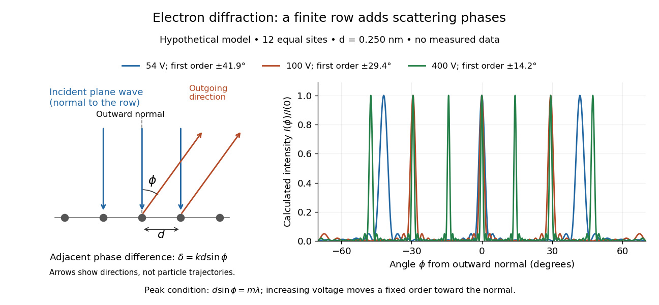
At , and the positive first-order angle is . At , the wavelength halves and this angle becomes about . Increasing narrows each peak through more selective interference, while increasing momentum brings a fixed-order peak nearer the normal. Unequal site amplitudes, multiple scattering, a three-dimensional crystal lattice structure factor, and finite detector acceptance can change this simple picture; it is an explanatory model with hypothetical inputs.
Articles by others on the same topic

Diffraction is a phenomenon that occurs when a wave encounters an obstacle or a slit that is comparable in size to its wavelength. It results in the bending and spreading of waves as they pass around the edges of the obstacle or through the slit. This behavior is observed with various types of waves, including sound waves, light waves, and water waves.