Solution
ID: past-exam-of-the-physics-2-paper-of-the-university-of-oxford/2019/10/a/solution
Past exam of the physics 2 paper of the University of Oxford 2019 10 a Solution by  Codex 0 2026-10-25
Use complex phasors with time dependence and assume an unloaded output. The capacitor has electrical impedance . The voltage divider formed with the resistor gives the transfer functionFor input , the output amplitude and phase shift areso .
Here , and the cutoff frequency is . This is an RC low-pass filter: at small frequency the capacitor has large electrical impedance and the output nearly equals the input; at large frequency it increasingly shunts the signal to ground. The amplitude then falls as , and the phase shift approaches .
| Frequency | Output amplitude divided by | Output phase shift \ | | | \ | | | \ | | | |
|---|
No numerical input amplitude is supplied, so the output voltages are specified as fractions of . An application is suppression of high-frequency electrical noise on a slowly varying signal. A finite load changes the transfer function and must be included if its electrical impedance is comparable with the circuit's output electrical impedance.
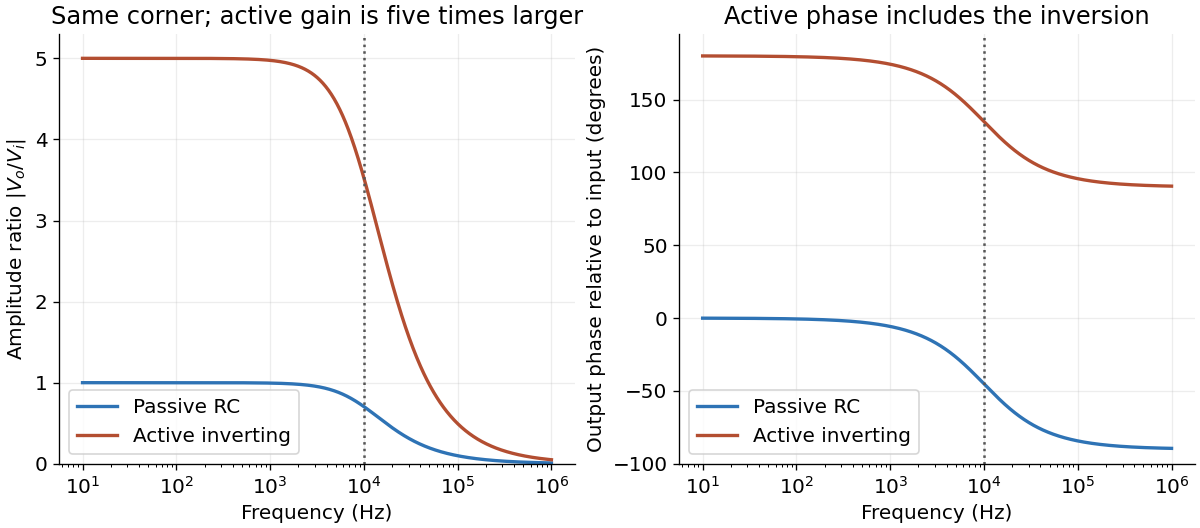
Passive and active low-pass amplitude and phase responses
. Details. 
New to topics? Read the docs here!