A voltage divider uses two resistors connected in series to obtain a fraction of an applied electric potential difference. Let the upper electrical resistance be , the lower one , and the input be relative to a common electrical reference potential. The output is the junction's electric potential difference relative to that same reference, across . The familiar ratio assumes zero output electric current: no external electrical load draws from the junction. In a steady direct current model with fixed resistors obeying Ohm's law and an ideal voltage source,Here is the open-circuit voltage; correspond to in the header formula. With no junction branch, Kirchhoff's current law makes the same electric current pass through both resistors, and Ohm's law gives the two voltage drops. For , division gives ; if , the predicted output is zero but this ratio is undefined.
An original stipulated example has and . With zero output electric current, and . An attached electrical load instead gives ; a load gives . These are exact model predictions, not measured readings or specifications of a particular multimeter or oscilloscope.
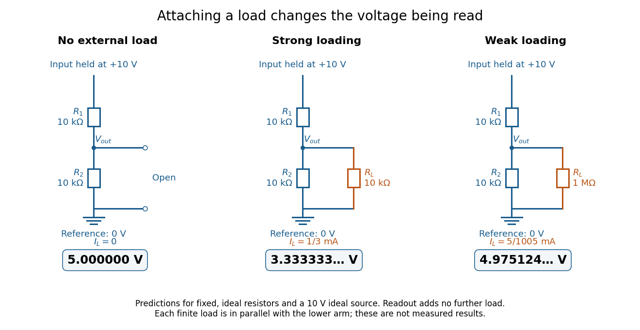
The same voltage divider has three different predicted outputs as the attached load changes
. Original circuit and readout comparison for ideal input and two resistors. Each finite connects across ; the displayed numbers are model predictions with ideal readout, not experimental data. Source. Details.The divider is useful for scaling a voltage or converting a change in a sensor's electrical resistance into an electric potential difference. Its beauty is also its trap: multiplying both electrical resistances by the same positive factor preserves the unloaded ratio, but changes the effect of any fixed electrical load. A divider therefore supplies a predictable ratio under specified loading conditions; it is not a source that maintains that voltage for arbitrary output electric currents. A Wheatstone bridge compares two divider junctions, while Thévenin's theorem describes the divider's response to many different loads.
Articles by others on the same topic


A voltage divider is a simple electrical circuit that produces an output voltage that is a fraction of its input voltage. It is typically used to generate a lower voltage from a higher voltage source and is often employed in applications such as signal conditioning, sensor measurements, and adjusting levels in electronic circuits. ### Basic Concept A voltage divider typically consists of two resistors, \(R_1\) and \(R_2\), connected in series across a voltage source (\(V_{in}\)).