RC low-pass step response
ID: rc-low-pass-step-response

The step response describes a sudden persistent input change. Suppose the input becomes a constant at , and the initial capacitor voltage is . Finite electric current leaves that voltage continuous. Subtract from the RC low-pass filter equation: the remaining error satisfies . Separating variables givesFor an initially uncharged capacitor and a to step in the constructed example,At one time constant, , the voltage is , about of its final value. The voltage error then continues its exponential decay. This is different from a pure delay: the output starts changing immediately, yet takes time to approach the target.
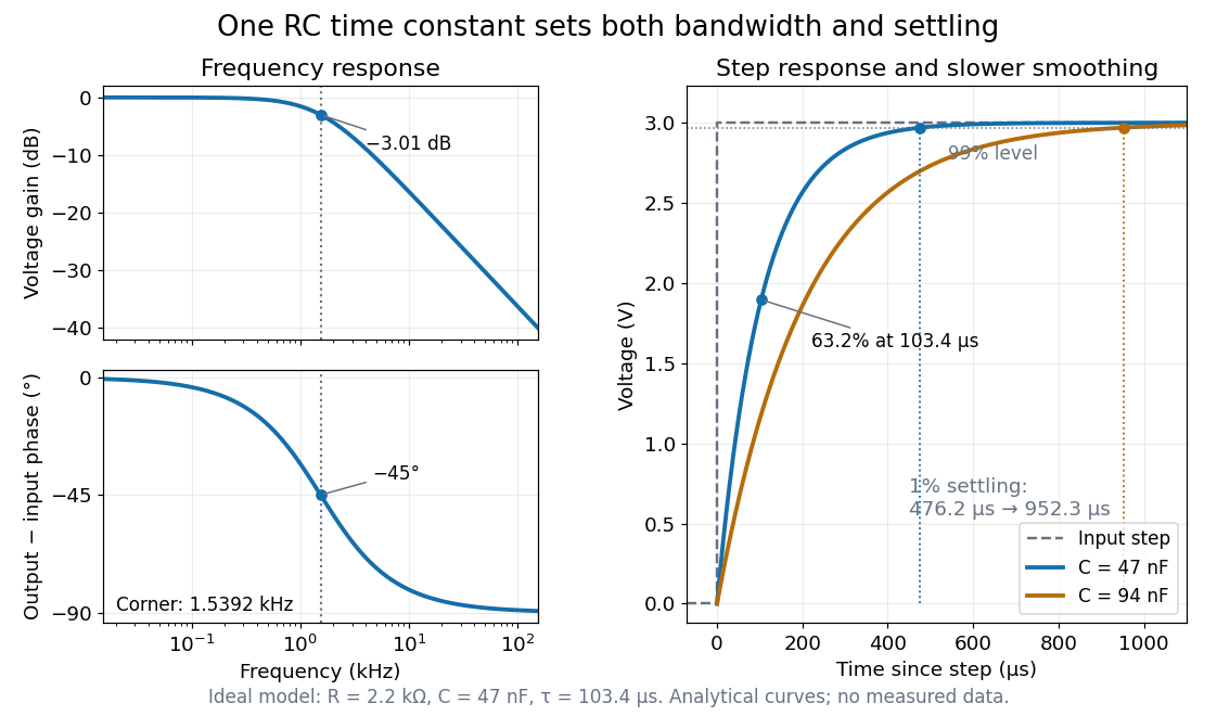

Define settling time relative to the total voltage change: require thereafter, with . The exponential decay is monotone, soFor settling, ; the to rise takes . Reducing the cutoff frequency by doubling doubles both times. This reciprocal relation is the useful connection between signal bandwidth and response speed: stronger suppression of rapid noise comes with slower tracking of wanted changes.
New to topics? Read the docs here!