Single-slit diffraction
ID: single-slit-diffraction

Single-slit diffraction is the spreading of light transmitted by one slit. Consider an ideal rectangular slit of width , illuminated normally by a uniform plane wave with a single wavelength in the surrounding medium. This monochromatic wave has uniform wave amplitude and equal incident wave phases across the slit, providing the required optical coherence. In the scalar Fraunhofer diffraction model, the normalized angular wave intensity isHere is measured from the forward normal in the plane across the slit width. The sinc function uses the unnormalized convention . The limit makes the central value one. This ideal envelope neglects additional direction-dependent propagation and detector factors; near the forward direction it describes the normalized screen irradiance. [ref]
https://openstax.org/books/university-physics-volume-3/pages/4-2-intensity-in-single-slit-diffraction. Ling, Sanny and Moebs, University Physics Volume 3, §4.2: single-slit intensity
.The noncentral zeros satisfyThe restriction follows from the range of the sine of a real angle. The first minima have when . If , this model has no noncentral zero in the forward hemisphere; equality puts the first zeros at grazing directions, outside the small-angle approximation and off any finite perpendicular screen. [ref]
https://openstax.org/books/university-physics-volume-3/pages/4-1-single-slit-diffraction. Ling, Sanny and Moebs, University Physics Volume 3, §4.1: positions of diffraction minima
.For , define the central width as the separation between the two first minima. Its angular width and its width on a perpendicular screen areThe angular approximation uses radians and requires ; the screen approximation uses . The tangent relation is exact straight-line geometry, even though the underlying Fraunhofer diffraction field is approximate. This width is distinct from the full width at half maximum.
For , and , the positive first minimum isThe dimensionless far-field parameter is . Doubling the slit width to gives and parameter ; both curves below use the Fraunhofer diffraction approximation. Choosing halves those parameters and doubles both screen widths.
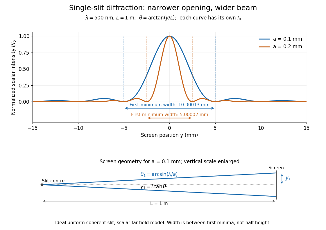

Each curve is normalized to its own ; the arrows measure between first minima. The calculation uses before evaluating the sinc function, rather than replacing by . The lower diagram shows the exact screen geometry with the vertical scale enlarged. Normalization removes the change in peak brightness when the slit width changes.
The wave interference explanation is especially simple: divide the slit into equal narrow strips and add their complex amplitudes, rather than their wave intensities. With wavenumber , the continuous slit givesIntegrating the complex exponential gives the endpoint difference; its continuous value at zero is one. Taking the squared complex modulus gives the stated wave intensity. This is the Fourier transform of an interval indicator expressed in angular coordinates. Feynman's continuous-source argument obtains the same pattern by letting the number of sources tend to infinity. [ref]
https://www.feynmanlectures.caltech.edu/I_30.html#Ch30-S2. Feynman, Leighton and Sands, I §30–2: continuous distributions of oscillators
.At the positive first minimum, the wave phases span exactly across the slit. Every strip in one half has a partner away, with equal wave amplitude and phase difference , so the pairs cancel. At , all the wave phases align instead. [ref]
https://openstax.org/books/university-physics-volume-3/pages/4-1-single-slit-diffraction. Ling, Sanny and Moebs, §4.1: cancellation between the slit halves
.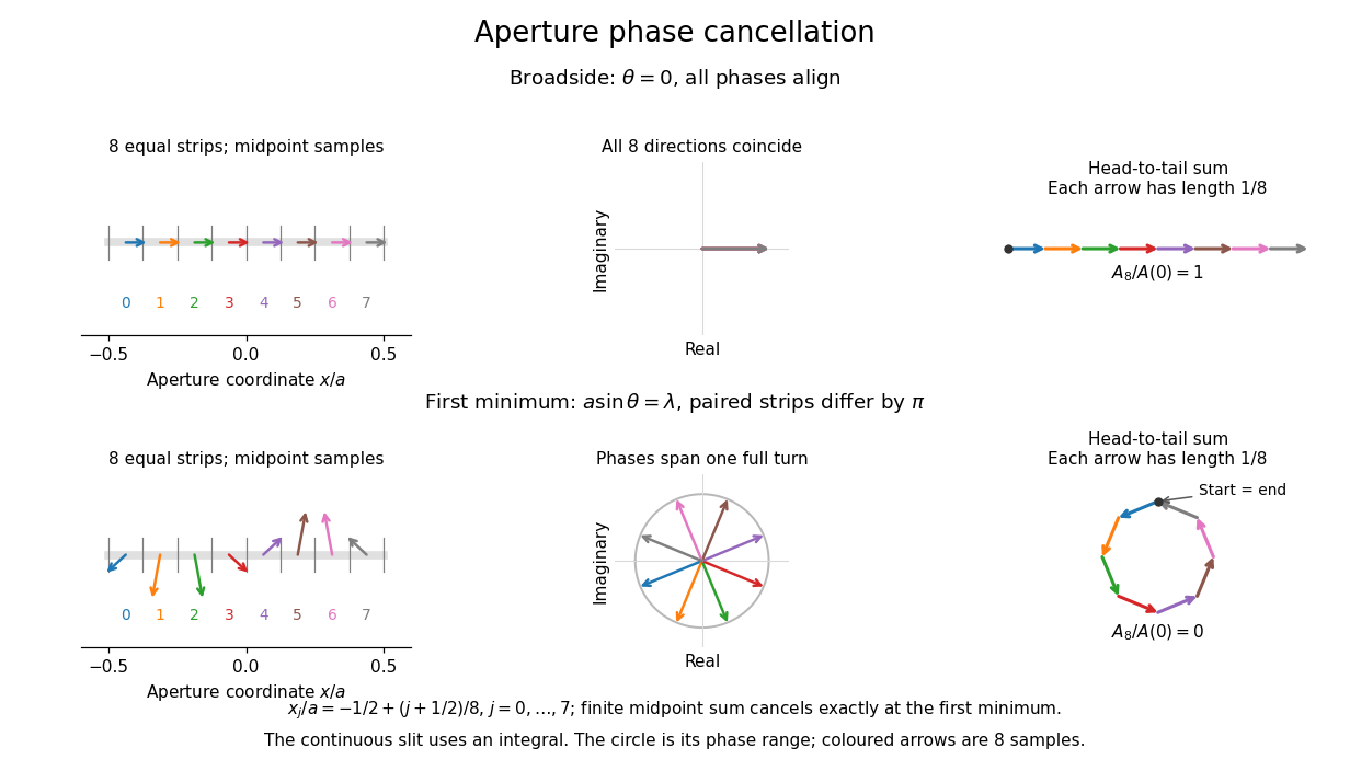
Complex amplitudes across a slit: aligned contributions at broadside and cancellation at the first minimum
. Details. 
The drawing uses equally weighted midpoint samples , with . At the first minimum their complex amplitudes are a common rotation of the eight roots of unity, so their head-to-tail polygon closes exactly. This finite sum illustrates cancellation; the continuous integral, rather than eight point sources, defines the slit pattern at general angles. The circle shows the continuous range of wave phases; coloured arrows show the eight samples.
A narrower aperture requires a larger angle to accumulate the cancelling phase difference, so narrowing the slit widens the beam. This is a useful limit on geometrical optics: confining light more tightly at an opening increases its subsequent angular spread. At fixed incident irradiance and slit height, reducing also reduces transmitted power, exposing a practical balance between diffraction-limited resolution and light throughput. In a diffraction grating, this single-slit diffraction envelope modulates the wave interference between different slits.
New to topics? Read the docs here!