A cardiac long axis is a base-to-apex direction used to describe the heart or a specified ventricular chamber. In left-ventricular imaging it is commonly planned through the cardiac apex and the center of the mitral valve. It is a chamber-based anatomical reference, not necessarily the vertical direction of a patient's body or an image display.
The primary cardiovascular magnetic resonance imaging protocol specifies connected two-chamber, four-chamber and short-axis planning from anatomical landmarks.[ref]
Standardized cardiovascular magnetic resonance imaging (CMR) protocols: 2020 update by Christopher M. Kramer and others. General techniques, Left ventricular structure and function, items 3 and 6; Figures 1–3
A long-axis image plane contains the chosen cardiac long axis; the corresponding cardiac short axis describes a transverse direction or view. Different planes can contain the same long-axis line while displaying different walls and neighboring chambers.An original vector construction makes the distinction precise. Let be the apex position and a chosen basal reference point. Thenis the axial unit vector. A displacement has axial component and transverse component . The line alone does not determine how the transverse coordinates are rotated around it.
This geometry matters for cardiac image foreshortening. In a simple projection model, a length tilted by out of the display plane projects to . A 10 cm length tilted by appears about 8.66 cm long. This is a geometrical illustration, not a correction formula for a tomographic slice: a slice may miss the true apex rather than project it. Consistent landmark selection is therefore part of meaningful comparisons of cavity shape, motion and volume.
Cardiac image foreshortening occurs when a cardiac view represents a shorter apparent base-to-apex extent than the intended anatomical chamber length, often because the imaging plane misses the true cardiac apex. It can create an apparently thick false apex and affect derived ejection fraction and deformation measurements.
A primary echocardiography study acquired optimal and deliberately foreshortened views in 72 participants using a GE Vivid E9 system. The altered acquisition window was one rib-space above the optimal window; two analysis systems were used to compare derived quantities.[ref]
Impact of apical foreshortening on deformation measurements: a report from the EACVI-ASE Strain Standardization Task Force by Serkan Ünlü and others. Abstract, Aims and Methods and results
This tests acquisition geometry while keeping the participant the same, rather than interpreting every shorter-looking chamber as a biological change.An original ellipsoid model distinguishes a missed apex from a simple projected length. Letwith the true cardiac long axis along . The central long-axis plane includes both axial tips and has full length . A parallel offset plane instead intersects an ellipse whose apparent axial extent isAt , . A 10 cm true extent therefore appears as 8 cm in this model even though the slice was translated rather than rotated. Its apparent tips are not the original chamber tips.
This model is a geometrical explanation, not a clinical correction formula. A shorter outline can alter measured volume differently at end-diastolic volume and end-systolic volume; the ejection fraction error need not follow the length error by one fixed percentage. Consistent anatomical landmarks and independent views help distinguish actual chamber shape from the chosen section. Improving the repeatability of an outline inside an incorrect plane does not recover anatomy that was never acquired.
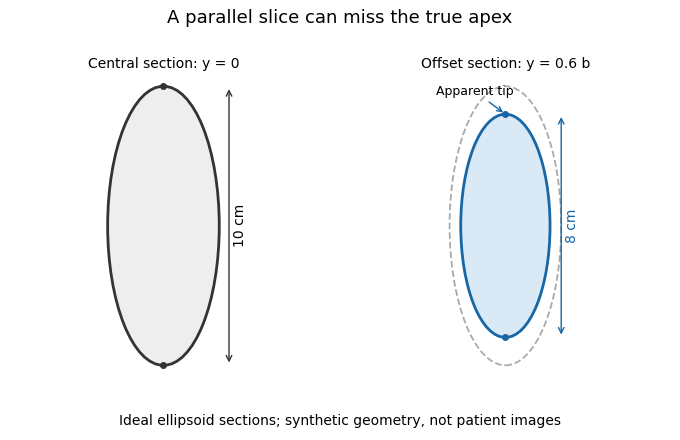
A parallel cardiac slice can miss the true apex
. Original sections of an ideal ellipsoid with axial semiaxis 5 cm and transverse semiaxis 2 cm. The central plane has full length 10 cm; a parallel plane offset by 0.6 times the transverse semiaxis has length 8 cm. Dashed outline shows the central section for comparison. Synthetic geometry, not patient data. Details.
Articles by others on the same topic
There are currently no matching articles.