A dipole antenna uses two conducting arms carrying an oscillating current, commonly fed across a central gap. Its changing charge and current distributions produce electromagnetic radiation. A short straight dipole has far-zone power proportional to relative to its axis: it radiates most strongly sideways and has axial nulls. A practical half-wave dipole has a nonuniform current distribution and a different exact pattern and input impedance. Geometric wire length, electrical length and the surrounding dielectric or conducting structures all affect resonance and matching.
A Hertzian dipole is an ideal electrically short oscillating electric dipole used to model radiation from a localized current element. In vacuum its far-field electric dipole radiation has angular power distribution and total power , evaluated at the retarded time. The electric-dipole approximation for radiation requires a source much smaller than its radiation wavelength.
A uniform electrically short current element of length with sinusoidal peak current has electric dipole moment amplitude . The mean electric dipole radiation power is , so fixing current makes it proportional to , rather than . Current, charge excursion and dipole moment are different quantities to hold fixed when comparing antennas. The approximation requires and does not impose the nonuniform standing-current profile of a long antenna.
For lossless parallel Hertzian transmitting and receiving dipoles separated by distance at angle to their common axis, directional gains are each . The emitted polarization matches the receiving axis's transverse projection. Matched-load power is therefore . One angular factor describes transmission and the other reception. This assumes reciprocal ideal dipoles, conjugate matching, far-field separation and negligible dissipative loss.
For a lossless ideal Hertzian dipole driven by an incident wave, use its induced open-circuit voltage and its feed impedance . A conjugately matched load has impedance . The same induced current therefore delivers equal power to the load and to radiation resistance: . The scattered wave has the usual dipole angular pattern. In direction of gain , its scattering cross-section is , since the load receives .
This ideal single-mode scattering is not the same as a signal that travels through an already matched antenna port, reflects from a mismatched terminating load, and returns. A zero port reflection coefficient removes that latter echo but does not make the physical dipole invisible to the incident field. Additional structural scattering, ohmic loss or a different load changes the result.
Articles by others on the same topic

Radio Wave Properties: Electric and Magnetic Dipole Antennae by Harvard Natural Sciences Lecture Demonstrations (2020)
Source. The dude lights bulbs on an antenna made of a single piece of copper, powered with EM radiation. Amazing.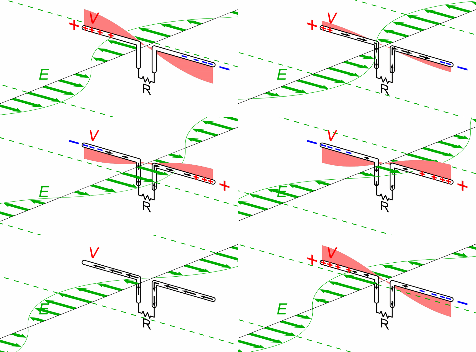
Dipole antenna receiver animation
. Source. 
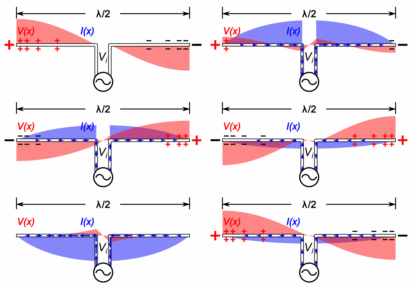
Dipole antenna transmitter animation
. Source. 