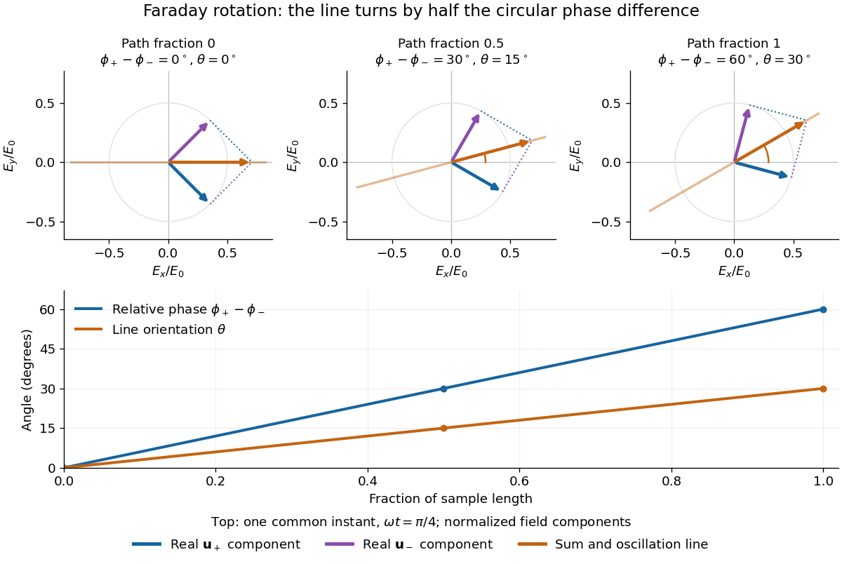
The factor of one half follows from superposition, without assigning ambiguous right/left names to the circular polarizations. Use the complex amplitude convention and fixed transverse unit vectorsFor equal transmitted wave amplitudes, let the accumulated wave phases be and . Their sum isThe common wave phase sets the timing of the electric field oscillation; the real direction in parentheses sets its linear polarization. Opposite circular polarizations have changed their relative wave phase, yet their sum still oscillates along a line. Unequal transmitted wave amplitudes would generally give elliptical polarization instead.
In a uniform sample, with refractive indices and vacuum wavenumber , the phase difference is . ThusThe second relation identifies the small signed circular birefringence responsible for the rotation in this basis. Unlike a waveplate, whose separated modes have orthogonal linear polarizations, this ideal rotator has modes with opposite circular polarizations.

Articles by others on the same topic
There are currently no matching articles.