The polarization of an electromagnetic wave describes the path traced by its transverse electric-field vector at a fixed point. A monochromatic wave may be linearly, circularly, or elliptically polarized; in vacuum it has two independent transverse polarization states.
For a vacuum plane electromagnetic wave, a Lorentz boost multiplies both transverse Jones vector amplitudes by the same positive Doppler factor when the basis is carried to the aberrated ray. Their ratio and phase difference therefore remain unchanged. All Stokes parameters gain the same squared factor, leaving normalized parameters, ellipse shape, handedness and degree of polarization unchanged. This does not mean the propagation direction or the components in an arbitrarily fixed pair of spatial axes remain unchanged.
The Faraday effect is magnetic field-induced circular birefringence: opposite circular polarizations acquire different wave phases, rotating transmitted linear polarization. For a transparent medium with isotropy before applying the magnetic field, in the linear magnetic-response regime at fixed vacuum wavelength and temperature ,Here is the Verdet constant, is the material path length, and is the applied magnetic flux density component along the ray. This is the external bias, distinct from the oscillating magnetic field of the light itself. Michael Faraday discovered the effect in 1845.[ref]
Faraday effect. RP Photonics Encyclopedia, Faraday Effect, Rüdiger Paschotta: What is the Faraday Effect?, rotation law and discovery
Fix the sign before using the formula. On the forward path choose a right-handed Cartesian coordinate system, propagation along , and measure from toward for the electric field's oscillation line. Positive is counterclockwise in the -right, -up end view seen from , looking toward the source. Then and positive means positive rotation for positive . This convention differs from the clockwise-positive convention in optical rotation. A linear polarization line is unchanged by ; a measured orientation determines accumulated rotation only modulo , unless continuity selects a branch.
For uniform , the formula reduces to . Its appeal is that a weak change of refractive index becomes a visible change of orientation. Magnetic reversal measurement of Faraday rotation turns this into an inference of or of the magnetic field path integral. Faraday rotation on a round trip explains the directional behavior used by an optical isolator. In an astronomical cold plasma, the high-frequency limit instead leads to the rotation measure law ; that wavelength dependence is not a universal law for transparent solids.
The Verdet constant is the coefficient relating Faraday rotation to the magnetic flux density path integral. Its SI units are . It depends on material, wavelength and temperature; a sign requires the stated viewing convention.[ref]
Faraday effect. RP Photonics Encyclopedia, Faraday Effect, Rüdiger Paschotta: What is the Faraday Effect? and Verdet Constants of Materials
The name commemorates Émile Verdet. For nonuniform material or temperature, use when the local scalar description remains valid. A single central magnetic field reading cannot generally replace this weighted integral. Strong additional linear birefringence or appreciable circular dichroism requires following the full polarization of an electromagnetic wave, rather than treating the output as merely a rotated line.
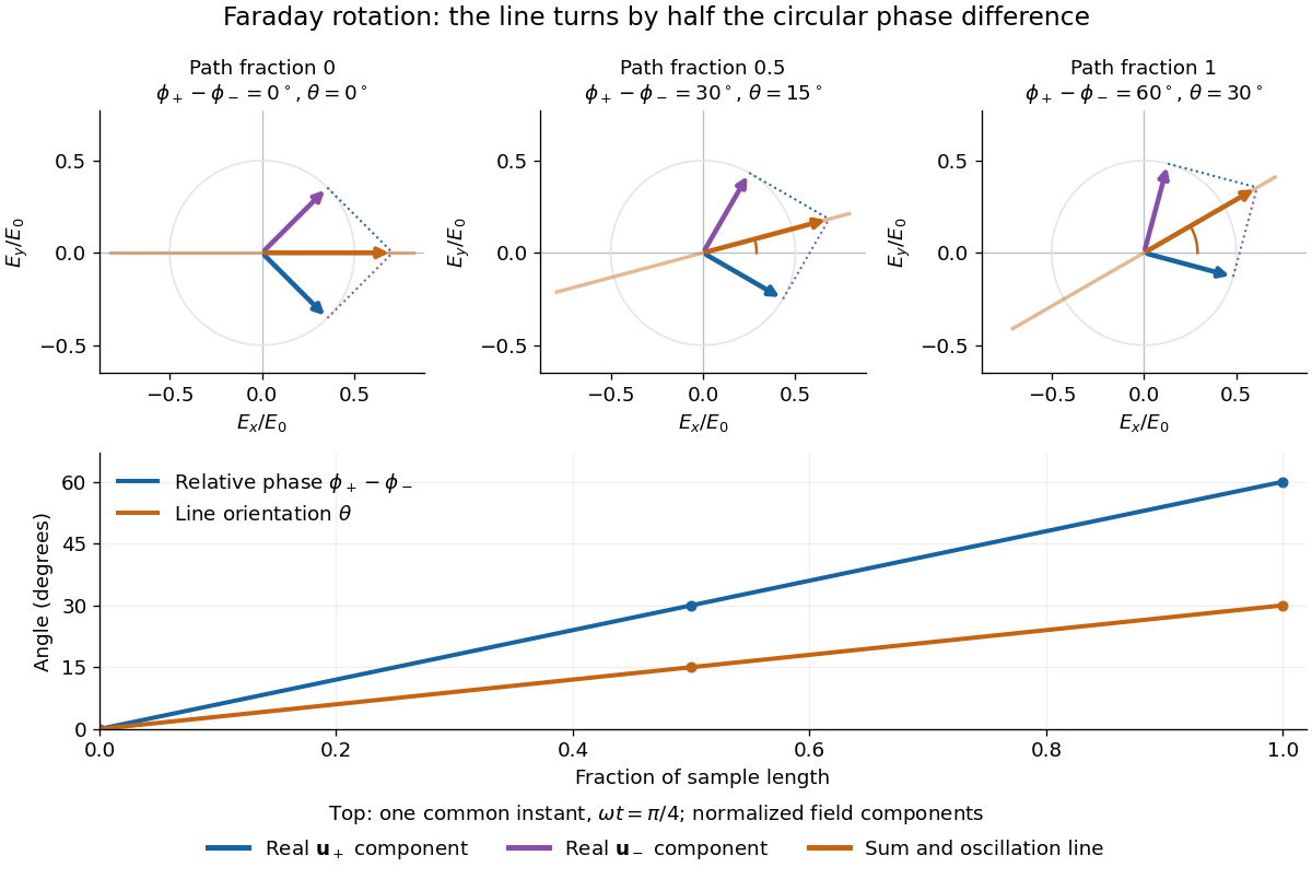
The factor of one half follows from superposition, without assigning ambiguous right/left names to the circular polarizations. Use the complex amplitude convention and fixed transverse unit vectorsFor equal transmitted wave amplitudes, let the accumulated wave phases be and . Their sum isThe common wave phase sets the timing of the electric field oscillation; the real direction in parentheses sets its linear polarization. Opposite circular polarizations have changed their relative wave phase, yet their sum still oscillates along a line. Unequal transmitted wave amplitudes would generally give elliptical polarization instead.
In a uniform sample, with refractive indices and vacuum wavenumber , the phase difference is . ThusThe second relation identifies the small signed circular birefringence responsible for the rotation in this basis. Unlike a waveplate, whose separated modes have orthogonal linear polarizations, this ideal rotator has modes with opposite circular polarizations.

Faraday rotation exhibits optical nonreciprocity: with the bias magnetic field held fixed, a retracing beam gains another rotation in the same laboratory sense. Natural optical activity in a reciprocal medium instead unwinds on retracing the path.[ref]
Faraday effect. RP Photonics Encyclopedia, Faraday Effect, Rüdiger Paschotta: What is the Faraday Effect?, doubled rotation on a round trip
To reconcile this with the signed formula, retain the laboratory axes for comparing physical lines. For the backward ray choose a right-handed ray basis , , . Its magnetic flux density component is , so its local rotation increment is . But positive is negative laboratory : the backward increment is therefore in the laboratory orientation plot. Reversing the ray reverses both the longitudinal component and the basis used for its signed angle. Reversing only one creates the false prediction of cancellation.
In fixed laboratory transverse components, define the rotation matrixFor an ideal mirror at normal incidence that contributes the same complex amplitude factor to both transverse components, the round-trip map is . The common mirror factor does not change the oscillation line. A reciprocal natural rotator instead gives . This comparison assumes a retraced straight path and no additional polarization-changing elements.
For example, a chosen single-pass Faraday rotation produces a returned line at to the original laboratory axis. A chosen reciprocal natural rotator returns it to . The same addition makes an ideal optical isolator possible: polarizers at and surround a Faraday rotator. Forward light follows and passes. Returning light selected at reaches at the entrance polarizer and is rejected by Malus's law. Real transmission loss and incomplete extinction limit the isolation.
Consider an original model at fixed vacuum wavelength and temperature . Stipulate a transparent sample with Verdet constant , length , uniform adjustable , and a field-independent analyzer-zero offset . These are chosen values, not measured glass properties. On a continuously tracked small-angle branch,Taking half the difference gives ; half the sum recovers . Hence . A field-reversal difference of is twice the single-field rotation, not that rotation itself. More generally this subtraction removes every contribution that is even under , provided the sample and apparatus remain otherwise matched.
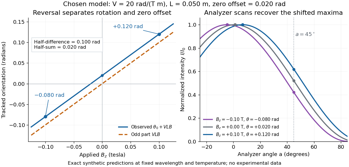

An ideal polarimeter analyzer at laboratory angle reads normalized light intensity . Here is the light intensity immediately before the analyzer, separately calibrated for each condition. A scan locates the maximum at modulo . At , expansion about zero gives , with angles in radians. At crossed extinction, the response instead begins as and loses the sign near zero. The favorable slope follows directly by differentiating Malus's law; its sign reverses if the angular convention is reversed.
A William & Mary teaching experiment places a glass rod inside a solenoid. Align a polarized helium-neon laser through the rod's centre onto a photodiode after a rotatable polarimeter analyzer. First scan the analyzer from maximum to minimum transmission in steps and record detector voltage, establishing the angular response. A function generator and electronic amplifier then drive sinusoidal electric current through the solenoid; a multimeter measures the electric current and an oscilloscope reads the photodiode. Trigger the oscilloscope from the generator, remove the large constant detector component by AC coupling, and average repeated traces. Convert the small synchronized voltage modulation to rotation using the calibrated angular slope. The manual fits rotation against magnetic flux density, using its stated coil calibration and converting measured root mean square current to peak current. This is a specified laboratory procedure, rather than measured results reproduced here.[ref]
Faraday Rotation. Physics 251: Experimental Atomic Physics, Fall 2019; William & Mary, Faraday Rotation laboratory chapter: printed pp. 2–7, apparatus, alignment, analyzer calibration, synchronized readout and equations (1.8)–(1.9)
To test the inference, add matched zero-electric current readings before and after each reversal, hold the analyzer fixed during paired readings, and compare equal positive and negative electric currents. A blocked beam tests electrical pickup in the detector channel. These are proposed controls. Joule heating scales as current squared, so reversing electric current at equal magnitude helps separate an odd rotation from even heating effects; it does not remove drift between readings. Record temperature and allow repeatable settling. Changes in transmission, mechanical motion, stressed-glass birefringence and detector pickup can imitate a signal. Synchronized averaging suppresses unsynchronized noise, but cannot reject an artifact synchronized to the drive.
Quantitative extraction of the Verdet constant also needs the integral of magnetic flux density through the rod: a finite solenoid can have a nonuniform axial magnetic field. Use its calibrated path integral, or justify a uniform-field approximation; do not silently multiply a central field by the whole rod length. A signed reversal or phase-sensitive readout tests the part odd in applied magnetic field. Its agreement with the simple rotation law supports the model under these controls, rather than proving that every change of transmitted light intensity is Faraday rotation.
For the high-frequency Faraday effect in a cold plasma, the rotation measure is the coefficient in . It is a density-weighted line integral of the line-of-sight magnetic field; the coefficient depends on the units. A sign convention for the line of sight fixes its sign. Correlations across an extended source can constrain a foreground magnetic energy spectrum, subject to statistical assumptions.
For constant electron density, common path length , and a solenoidal isotropic spectral tensor, the rotation-measure correlation contains the window . As becomes large compared with the correlation length, this window acts as within the integral. The transverse projector then has component one, yielding the displayed two-dimensional Fourier transform. For finite , the windowed integral retains longitudinal modes and endpoint corrections. The method of using such rotation measure correlations to infer magnetic spectra is developed by Enßlin and Vogt.
Invert the two-dimensional Fourier transform in the long-path projection of a magnetic correlation, then perform the angular integration in polar coordinates. The angular integral is , a Bessel function of the first kind, giving the displayed Hankel transform with the stated Fourier-Hankel normalization for an isotropic spectrum. The result recovers the scalar tensor coefficient , whose shell-integrated magnetic energy spectrum has an additional factor .
A linear polarizer transmits one linear polarization and suppresses the orthogonal one. Two ideal crossed polarizers block light unless an intervening medium changes its polarization of an electromagnetic wave. A twisted nematic field effect uses this selection to convert field-driven reorientation into brightness modulation.
A reciprocal optical circular polarizer can be assembled from a linear polarizer followed by a quarter-wave plate whose axes make to the transmitted linear state. Forward passage converts unpolarized light into circular light of half the ideal incident intensity. Reverse passage encounters the retarder first; it leaves unpolarized light unpolarized until the linear polarizer transmits half as linear light. Thus the one-pass intensity can be equal in both directions even though the outgoing polarization differs. Use a coherency matrix, not a single Jones vector, for unpolarized input.
The Stokes parameters describe intensity, two linear-polarization components and circular polarization. and depend on the chosen transverse basis. On the celestial sphere, transform as spin-two fields rather than as ordinary scalars.
A wave is linearly polarized when its oscillating electric field always lies along one fixed line. For a transverse plane wave, that line is perpendicular to the wavevector. Unlike circular polarization, the field oscillates along the line rather than rotating through directions.
An electromagnetic wave has circular polarization when its transverse electric field has constant magnitude and rotates once during each period. In complex-amplitude notation, two orthogonal components have equal magnitude and a relative phase of one quarter-cycle.
Articles by others on the same topic
There are currently no matching articles.