A waveplate uses birefringence to change polarization of an electromagnetic wave through phase retardation. Its fast axis has the smaller refractive index, hence the larger phase velocity; its slow axis has the larger index. Consider normal incidence with the optic axis in the plate face, so both components follow the same straight path. A linear polarization at to these axes excites equal wave amplitudes.
A complementary experiment uses two sheet polarizers with a cellophane sheet between them. First cross the polarizers and remove the sheet: the field is dark. Insert and rotate the sheet about the beam: light returns at intermediate orientations, but extinction recurs at two perpendicular orientations. The sheet has changed the polarization of an electromagnetic wave, without requiring a resolved double image. With white light, different wavelengths can produce different transmitted colors.[ref]
The Feynman Lectures on Physics, Volume I by Richard Feynman and others. I §33–3, Fig. 33–3 and the paragraphs describing removal, rotation and white-light colors of cellophane
. Brightness alone does not establish circular polarization: an ideal rotating linear polarizer also gives orientation-independent light intensity for unpolarized light.For the overlapping monochromatic wave components, let be the thickness and the vacuum wavelength. Define using the slow and fast refractive indices. With complex amplitude convention , the accumulated slow-minus-fast phase difference isThis is the optical path difference expressed as a wave phase. It is a signed accumulation convention; with the opposite time convention the sign reverses. The outgoing polarization of an electromagnetic wave depends on modulo . Here the positive slow-minus-fast differs from the signed principal-index used in the parent birefringence entry when .
For an original worked example, stipulate at and a uniform thickness . These are design assumptions, not measured material data. The optical path difference is , soIt is a quarter-wave plate. At the same wavelength and refractive indices, doubling to gives , a half-wave plate. A thickness increase changes by , or ; retaining the same birefringence at would instead give for the plate. Real refractive indices also vary with wavelength, so this last calculation explicitly neglects optical dispersion.
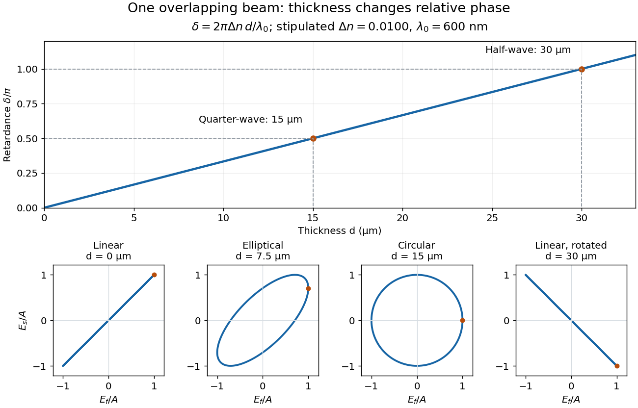
Phase retardation grows with thickness while overlapping components change polarization of an electromagnetic wave
. The stipulated , model gives quarter-wave and half-wave thicknesses of and . Insets trace the normalized electric field at a fixed point for equal fast/slow wave amplitudes, with and . The intermediate ellipse, circle and rotated line require no spatial beam separation. Details.
For these equal transmitted wave amplitudes, orthogonal projection onto a polarizer crossed with the initial linear polarization gives a simple independent readout. After removing a common wave phase, the component complex amplitudes are proportional to ; orthogonal projection onto gives . Squaring its modulus yields : zero at , one half at , and one at . This assumes ideal polarizers, negligible specular reflection and wave absorption, overlapping components and stable relative wave phase. It measures a periodic function of phase retardation, so one brightness measurement cannot determine the thickness uniquely.
A quarter-wave plate gives a quarter-cycle phase retardation. Equal transmitted wave amplitudes initially in linear polarization at become circular polarization; unequal wave amplitudes generally give elliptical polarization. Reversing the sign reverses the traversal of the same circle.
A half-wave plate reverses the relative sign of the two components. For initial linear polarization at angle to the fast axis, the outgoing line is at modulo . The input therefore rotates by .
Articles by others on the same topic
There are currently no matching articles.