Pearlite is a microstructural arrangement of two phases, ferrite and cementite, rather than a single phase. Ferrite is an iron-rich solid solution; cementite is the carbide . A pearlite colony contains alternating lamellae of these constituents formed by transformation of austenite.
A thermodynamic phase has a specified crystal structure and composition range with locally homogeneous properties on the appropriate scale. The word pearlite instead describes how distinct phases are arranged. Its lamellar spacing and orientation can change while the identities of its two phases remain the same.
Use the line fraction occupied by the tall narrow ridges as an estimate of cementite volume fraction, assuming the line is representative and its etched height classification identifies the phases correctly. The displayed profile gives roughly cementite and ferrite.
An operational measurement at a height threshold near gives four ridge widths totaling about over a profile about long:Changing the threshold over a reasonable part of the high ridges gives roughly –, so this is an image-based estimate, not an exact phase analysis. The occasional low protrusions should not all be counted as full cementite lamellae merely because they are above a noisy baseline. The reference line and threshold convention must be stated.
For eutectoid pearlite, apply the lever rule between ferrite and cementite at the transformation temperature. Using standard approximate Fe–C values , and in weight percent carbon,These are mass fractions. To compare with an unbiased geometric line fraction, convert using the phase densities:With representative densities and , this gives about cementite and ferrite. Because the densities are similar, the mass and volume fractions differ only modestly. The phase-diagram values here are conventional approximations, not a claim that the exact 2018 Data Book has been recovered.
The profile estimate and equilibrium lever-rule estimate need not agree exactly. The height trace contains only four major ridges, making it a small sample of the microstructure. Pixel size, ridge-threshold choice, tip geometry, contamination, polishing damage and unequal etching change apparent widths. A finite-radius AFM tip can broaden the narrow raised cementite regions, biasing their inferred fraction upward.
The equilibrium calculation assumes eutectoid pearlite with the chosen carbon composition and tie-line values. Off-eutectoid steel can include proeutectoid ferrite or cementite outside the pearlite; alloying, carbon segregation and non-equilibrium cooling alter the simple Fe–C estimate. Carbon solubility also varies with temperature. The mass-to-volume conversion requires phase densities.
The observed difference between roughly ridge fraction and equilibrium phase volume is therefore a reason to examine sampling and the etched-surface measurement, not to force the image widths to match the lever rule. Multiple colonies, repeated calibrated traces and a phase-sensitive measurement would improve the comparison.
Ferrite etches faster in Nital, so it recedes and leaves cementite standing as the higher ridges. The identification is based on the surface-relief preparation, not on assuming that every bright feature in every microscopy mode is cementite. In the stated AFM image, brightness is a displayed height contrast.
The lamellar interfaces now make with the surface normal, or with the surface itself. Draw inclined alternating plates rather than vertical stripes, with preferentially etched ferrite below the more resistant cementite.
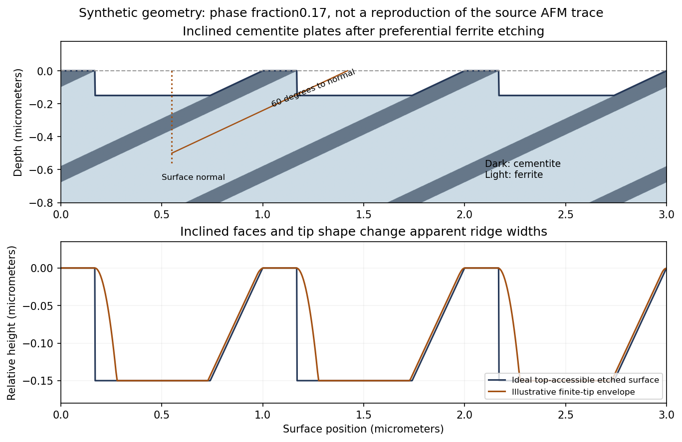
Original inclined-lamella etching geometry and illustrative AFM profile; the synthetic spacing and fractions are not a tracing of the source data
. Details. 
The upper panel shows an inclined microstructure intersecting the original plane. Differential etching can expose a shallow inclined cementite face on one side of a ridge and an undercut or overhang on the other. The lower panel shows its accessible height profile, with additional rounding from a finite tip. It is therefore possible to obtain an asymmetric ridge even from an initially planar section through parallel lamellae.
For an ideal unetched planar cut, a plate of normal thickness has apparent surface widthThe same factor applies to the ferrite spacing. Inclination alone broadens all intersections together; it does not by itself change the true phase-width ratio.
The danger is identifying an etched height interval with the original planar phase intersection. Preferential ferrite dissolution exposes inclined cementite faces and can produce overhangs. A conventional AFM tip cannot follow a reentrant underside; its finite size also broadens ridge tops and may not enter the intervening troughs. A thresholded height width can consequently differ from both the true plate thickness and its original surface intersection.
A uniform inclination at an ideal flat cut does not itself invalidate a line-fraction estimate: both phases acquire the same geometrical width factor, which cancels in their ratio. The problem is differential relief and probe accessibility after etching, together with uncertain local angles and limited sampling. Using only the apparent ridge occupancy can overestimate cementite. An independently polished section, calibrated probe geometry, several directions and colonies, or another phase-sensitive method is needed to test the inference.
Articles by others on the same topic
There are currently no matching articles.