The telescope forms the sky image at the entrance slit. A collimator makes the transmitted beam parallel, a reflection diffraction grating disperses it, and a camera’s optical lens focuses each wavelength to a different detector position.
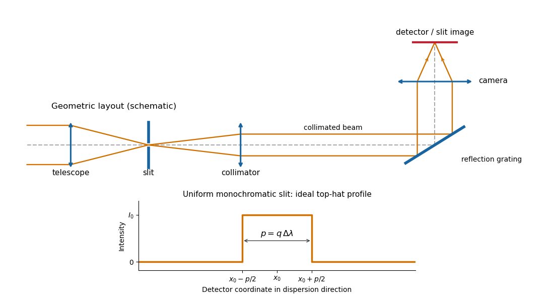
Reflection-grating spectrograph and slit-limited line profile
. Details. 
With a uniformly illuminated slit, ideal imaging and negligible slit diffraction, each monochromatic slit image has an approximately top-hat intensity profile of physical width . A small wavelength separation displaces two such images by , using the positive magnitude of grating dispersion. In the geometrical, slit-limited convention, resolution occurs when the displacement is of order the slit-image width. HenceHere is the slit’s apparent wavelength extent. A finite diffraction grating broadens the sharp edges; the top-hat sketch and the following identities presume slit-limited resolving power of a grating, rather than the regime where the grating’s own diffraction determines the line width. A precise resolution criterion for nonideal profiles can change order-unity factors.
Let the telescope and collimator have focal lengths , and let be the physical slit width. The collimated beam diameter in the dispersion direction is , so .
The diffraction grating changes both the angular width and the beam diameter. At fixed wavelength, differentiating the grating equation gives . Thus the anamorphic magnification of a grating givesIf is the illuminated surface length, its projected beam diameters are and . Multiplication cancels the anamorphic factors:ThereforeThis is a one-dimensional optical-invariant relation: a grating cannot independently magnify the slit and shrink the corresponding beam without compensating angular changes. The calculation uses local paraxial imaging about each instrument’s chief ray and an unclipped beam.
From the slit profile, the spectral resolving power obeys . Substitute into the preceding optical-invariant relation:The slit-image width cancels. Although is a detector length per unit wavelength, is a detector length, so this expression for has units of length, as does .
Use the signed-angle convention in which the reflection grating equation is , with positive diffraction order . For fixed incidence,The second identity is the local focal-plane scale, measured about the camera axis aligned with the central diffracted ray. Since , the projected beam size cancels the cosine in the grating dispersion:Writing for the number of illuminated grooves also gives . This connects the geometrical instrument invariant to the phase span of the illuminated diffraction grating.
Substitute the grating equation into the preceding result:Moving across the illuminated grating by one groove spacing changes the incident-plus-outgoing optical path length by . Across length , the total path difference is therefore . Thus is the optical path difference between contributions from the two ends of the illuminated grating.
The number of coherent phase cycles across it is , which is the intrinsic diffraction-limited spectral resolving power of the diffraction grating under the usual first-minimum criterion. In the slit-limited regime, also states how much sky angle can be accepted at a given resolution and aperture. Holding slit angle and resolution fixed while increasing telescope diameter requires a larger optical path span. The geometry gives ; large incidence and diffraction angles increase resolution per unit grating length, though grazing beams become impractical.
The slit equations do not imply unlimited resolution when tends to zero. Once is comparable to , finite-aperture diffraction matters and the actual resolving power is bounded by about .
Articles by others on the same topic
There are currently no matching articles.