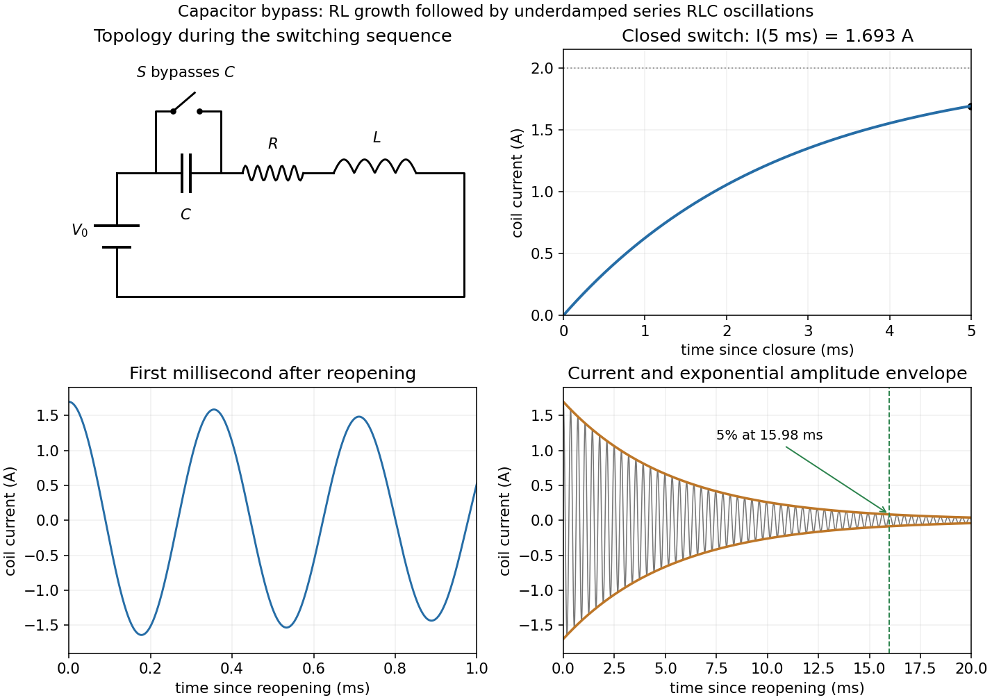
Initially the open switch leaves a series capacitor-resistor-inductor circuit driven by the battery. After a long time the electric current is zero and the capacitor voltage is . Closing the switch bypasses and, under the stated idealization, instantaneously discharges the capacitor. The inductor current remains continuous at zero.
The remaining RL circuit obeys , soThe capacitor's impulsive discharge through the ideal short is distinct from the finite electric current through the coil. A finite switch resistance would resolve that separate fast transient.
Put , , and . When the switch reopens, the circuit again contains the battery and all three series elements. Inductor current continuity and capacitor voltage continuity giveThus , not zero. Differentiating the loop equation gives the homogeneous current equationThe battery is still connected; its constant voltage disappears on differentiating, and the eventual capacitor voltage is .
With and , the inequality makes the circuit underdamped. The damped angular frequency and ordinary frequency areThe full current satisfying both initial conditions isIts amplitude envelope decays as . ThereforeThis is measured after reopening; on the clock starting with the first closure it is . An instantaneous current zero is not an amplitude decay measurement.

Articles by others on the same topic
There are currently no matching articles.