The source cover identifies this as the 7 June 2022 CP2 examination; the archive member is labelled
2021/T/a10288w1.pdf.Position A disconnects the battery and closes the resistor-inductor loop. Taking clockwise electric current as positive, Kirchhoff's voltage law for this RL circuit givesThe electric current through an ideal inductor remains continuous across a switch with no impulsive voltage. Thus , and separation of variables givesIf the switch remains at A, the same result holds for every . The time constant is ; the stored magnetic energy is dissipated by Joule heating.
Put and , with . The first interval leaves electric current . Position B reconnects the battery, so the driven RL circuit obeys . Multiplication by the integrating factor , or subtraction of the constant solution , givesConsequentlyThe same two intervals give the recurrence relation . Its fixed point is . Subtracting this fixed point makes the recurrence relation homogeneous:This is the upper endpoint of the eventual periodically switched RL circuit response, immediately before switching from B to A. The lower endpoint is . Their sum is , consistent with equal charging and discharging intervals.
An ideal operational amplifier has infinite input impedance, so neither input draws electric current, and zero output impedance, so its prescribed output voltage is independent of the output electric current within the ideal model. These are the two additional assumptions needed here.
The non-inverting input is grounded, so the finite voltage gain gives , or . Infinite input impedance makes Kirchhoff's current law at the inverting inputSubstitute and multiply by :Hence the inverting operational amplifier hasAs , the voltage gain tends to . Setting before taking that limit would discard precisely the correction being calculated.
Assume the electrical conductor is nonmagnetic, with magnetic permeability , and neglect end effects. Rotational symmetry and translational symmetry make the magnetic flux density azimuthal and constant along a coaxial circle. The magnetostatic Ampère law therefore givesUniform current density is , so . ThusThe direction follows the right-hand rule around the electric current. For a uniform linear magnetic material, replace by its magnetic permeability.
Write the axial current density as . Normalize it using the total electric current:The enclosed electric current at radius is . The magnetostatic Ampère law now yieldsBoth profiles join the exterior magnetic flux density at the surface, but the second vanishes quadratically at the axis because less electric current is concentrated near it.
Choose zero electrostatic potential at infinity. By Coulomb's law and the superposition principle, the two point charges giveHere is the vacuum permittivity. For a nondegenerate zero-equipotential curve, the electric charges must have opposite signs. Let be the two distances. The equation becomes , and henceFor a circle centred at the origin, its coefficient must vanish: . If and , this givesSubstitute in the constant term:ThereforeThis is an Apollonius circle: the distance ratio is constant. The distinct-position assumption matters. For example, , gives zero electrostatic potential everywhere away from the coincident point charges, so there is no distinguished zero circle. If only one position is at the origin and the other is not, no nontrivial positive-radius circle centred at the origin is possible.
In charge-free, current-free vacuum, Maxwell's equations areTaking the curl of the third equation and using the fourth, the curl of the curl identity, and the zero divergence of the electric field givesThe magnetic flux density obeys the same wave equation. For the plane wave factor , the spatial Laplacian contributes and the second time derivative contributes . Thusfor propagation in the positive direction. The zero-divergence conditions require , while the curl equations require . These conditions show that the proposed plane waves satisfy all four Maxwell's equations, rather than only their derived wave equations. Physical electric fields and magnetic fields are the real parts of the complex expressions.
Using directly with the specified plane wave givesThe electric field, magnetic flux density and propagation direction form a right-handed triad, and for a nonzero wave amplitudeThe electric field and magnetic field have the same wave phase in vacuum.
The distance from the origin to the incident straight light ray is (taking ). At its intersection with the sphere, let and be the angle of incidence and angle of refraction, measured from the radial normal vector. Elementary right triangle geometry gives . By Snell's law,The refracted straight light ray inside the sphere has distance from the origin. ThereforeThe angle describes the normal vector of the new line; it need not equal the propagation angle. The existence of a crossing requires . A signed convention for gives the same line equation after choosing the orientation of its normal vector consistently.
Approximate the atmosphere by concentric spherical layers of refractive index. At every boundary, Snell's law conserves , where is the angle between the light ray and the radius. Straight propagation between boundaries conserves the same quantity because is the distance of that line from the origin. In the smooth limit this is the spherical ray invariantAt the surface, a light ray apparently on the horizon is tangent, so . In vacuum far from the Earth, , and the straight incident line has distance from the centre. Removing the atmosphere while retaining that incident line gives minimum altitudeThe detailed variation of refractive index with altitude changes the local curvature of the light ray, but not the conserved . This conclusion assumes a spherically stratified atmosphere and a light ray which actually connects the surface to space; nonspherical structure or a trapping layer would require separate analysis.
Take coordinate across the slit and observation angle from its normal vector. Under Fraunhofer diffraction, the relative optical path difference from is . Uniform coherent illumination makes the complex amplitude proportional to the aperture integral:The light intensity is proportional to , soThe central value is the continuous limit of the sinc function. The first minima satisfy , if . Infinite slit height removes spreading in the other transverse direction; this expression describes the slit-width direction.
Strictly, distance alone does not ensure Fraunhofer diffraction: one also needs , so that quadratic aperture-dependent wave phase is negligible, or observation in a suitable focal plane. For example, , and have but ; the Fresnel diffraction correction is then substantial. The displayed result uses the intended far-field regime of the question and the usual scalar aperture approximation.
For viewing near the nadir, the required angular resolution isUsing the Rayleigh criterion with the first minimum of the single-slit diffraction pattern gives . Thus the minimum collecting width in that model isThe numerical coefficient depends on the aperture shape and the chosen resolution criterion. If the mirror has an unobstructed circular aperture, the Airy disk version of the Rayleigh criterion is , giving . The question does not specify mirror shape; follows the slit-width model of part (i).
Use the phasor convention and interpret impedance matching as conjugate matching for the maximum power transfer theorem. The load electrical impedance of the series circuit isFor , the condition equates the real parts and imaginary parts:These formulas require , and a passive realization with , evaluated at the matching angular frequency; if depend on , the equation for is implicit.
There is a convention ambiguity in the word “matched”. Literal equality , as required for equal bridge arms in part (b), instead gives and , requiring . The inductive cases below use conjugate matching; literal equality is impossible for either passive inductive configuration at a finite positive angular frequency because its electrical reactance is positive while that of the series RC impedance is negative.
Let the unknown series circuit contain electrical resistance and inductance . Its electrical impedance is . Thus , , and conjugate impedance matching is possible withAt this angular frequency, the inductor and load capacitor have opposite electrical reactances of equal magnitude. Literal equality of their separate electrical impedances is impossible; for example, gives versus for every .
For electrical resistance in a parallel circuit with inductance , add electrical admittances and invert:Conjugate impedance matching to the series RC impedance requiresIt is possible at a finite positive angular frequency exactly when , in which caseThe expression for follows by substituting this into the real part of . If , no such finite matching angular frequency exists. Under literal equality, both passive inductive configurations fail by the sign of their imaginary parts.
Let the source's top terminal have voltage phasor and its bottom terminal zero. Denote the left and right junctions by and . The two left resistors are equal, so at balance . Zero electric current through the ammeter requires , and therefore equal upper and lower right-arm electrical impedances:Write . Separating real parts and imaginary parts givesThe second equation implies . Subtract to obtainA finite balance with positive components requires , and then . This equal-ratio RC bridge uses equality of arm electrical impedances, independent of the conjugate-matching convention in part (a).
Detector convention. The stated negligible-electrical impedance ammeter is an ideal short circuit, whose actual terminal voltage is zero at every angular frequency. The nontrivial bridge output usually intended is the open-circuit junction difference, obtained with the detector removed or replaced by a high-input impedance voltmeter. Define its polarity byFor a detector of finite electrical impedance , its terminal voltage is insteadHere is the Thévenin equivalent electrical impedance, found by shorting the ideal source. This exhibits why the ideal-ammeter limit has zero terminal voltage even when the bridge is unbalanced.
At zero angular frequency, the lower right capacitor is an open circuit, while the upper right electrical impedance tends to . With the detector removed, no electric current flows down that branch, so and . ThereforeFor the connected ideal ammeter, the resulting electric current from right to left is , despite its zero terminal voltage. This follows from with .
At the balance angular frequency, and the two voltage dividers have the same ratio. ThusThis zero detector electric current is the operational condition used to find and .
As , both capacitors approach short circuits. Thus , , and the unloaded right junction tends to the source's top-terminal voltage. HenceThe connected ideal ammeter carries limiting electric current from right to left because . Reversing the output polarity reverses both nonzero open-circuit answers, without changing their magnitudes.
Set the grounded plane at and the real point charge at . The image charge at makes the electrostatic potential vanish throughout the plane. The uniqueness theorem for the electrostatic potential then identifies the physical solution in :The normal electric field is . Differentiation givesand thereforeFor the electric field points into the electrical conductor, consistently with negative induced surface charge density.
Apply the superposition principle to the result of part (a). If , then the exact normal electric field from the two real point charges and their image charges isFor , Taylor's theorem gives . Sincethe leading electric dipole result isThe electric dipole moment is . The circle is the zero of the leading normal electric field and hence of the induced surface charge density. Inside it, induced surface charge density is negative; outside it, positive. The tangential electric field is zero everywhere on the grounded electrical conductor, so the leading full electric field vanishes on that circle. The corresponding dipole-induced charge on a grounded plane integrates to zero over the whole plane: the negative central region is balanced by the positive exterior.
For finite , is only the leading-order zero. With and , the exact zero satisfies , giving . For example, inserting any in the exact expression at does not give zero. This is a controlled electric dipole approximation, not an exact finite-separation identity.
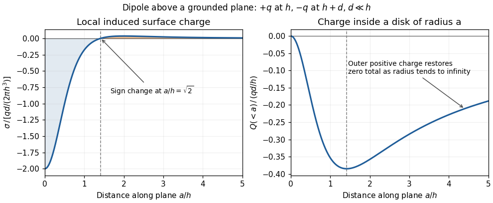
Sign reversal and enclosed induced electric charge for a normal electric dipole above a grounded plane
. Details. 
The electric field within a conductor in electrostatic equilibrium vanishes. The normal electric field boundary condition, with outward normal vector , therefore gives . Directly below the monopole, :For the electric dipole,The exact finite-separation answer iswhose Taylor series agrees with the boxed leading term. Although the real point charges have zero total electric charge, their unequal distances leave negative induced surface charge density immediately beneath them.
Use the source orientation, anticlockwise viewed from . The position and oriented line element areThe Lorentz force on the electric current element is . Evaluating the cross product givesEach component integrates to zero around , so . Equivalently, uniform magnetic flux density permits . Uniformity is essential; a nonuniform magnetic field can exert a net force on a magnetic dipole.
The elemental torque about the origin is . Substitution of part (a) givesOnly its component drives the allowed rotation about the axis. Using and , the projected torque isThe magnetic dipole moment is , so the full electromagnetic torque isIts component agrees exactly. The component is a real electromagnetic torque, but the bearing constraining motion to the axis supplies a cancelling reaction torque. For an allowed infinitesimal rotation , only does mechanical work.
Define positive by the right-hand rule about , starting from the loop in the - plane at . Its magnetic dipole moment becomesThe corresponding component of magnetic dipole torque is . Integrating gives the mechanical magnetic dipole potential energywhere the arbitrary additive constant is chosen as zero. Set . For , a positive-amplitude form isEquivalently, modulo . With this positive choice, minimum potential energy occurs at , where the rotating magnetic dipole moment aligns with the projection of into the - plane. If , the allowed torque vanishes, and is arbitrary. Holding electric current constant includes exchange with its supply; differentiating only the isolated loop's stored magnetic energy would not give the appropriate mechanical potential energy.
Write for transit time and for lens thickness to avoid using for both. In the thin lens approximation, the two geometrical distances to the lens plane are and . Their sum counts the lens segment as vacuum. Replacing that segment by material of refractive index adds to the optical path length. Thus, to the retained thin-element accuracy,Using the Taylor expansion for givesThe omitted geometrical terms include in optical path length, together with finite-thickness corrections discarded by the thin lens and paraxial approximations. The addition is , because the underlying distance already includes propagation across the thickness once in vacuum.
Fermat's principle makes the optical path length, or transit time in a stationary medium, stationary under small variations of the light ray with fixed endpoints. It need not be a global minimum. In the result of part (a), the coefficient of isFor a family of paraxial light rays from the object to its image, stationarity with respect to requires this coefficient to vanish. Therefore the thin lens equation isFor a distant object, , and the image position defines the focal length. HenceThe axial member is stationary by symmetry for arbitrary ; requiring the neighbouring non-axial light rays to meet the same image is what determines .
In surrounding refractive index , the geometrical segments contribute to the optical path length, while replacement by the lens adds . Fermat's principle therefore givesThe physical focal length measured in the surrounding medium isFor and , increasing from towards makes the positive focal length grow monotonically from its vacuum value to infinity: . At , there is no refraction at the boundary, so the element has zero optical power and no finite optical focus. If , its optical power changes sign and the same shape becomes diverging.
For the convex vacuum void, use internal refractive index , external refractive index , and the original in the immersed thin lens formula:A concave glass thin lens of the same curvature magnitude in vacuum has and thereforeBoth elements diverge, but their physical focal lengths differ by a factor for . For example, makes the void's focal length magnitude times that of the concave glass element. Their reduced optical powers are equal; physical focal length also depends on the surrounding refractive index.
Source paper: www.whatdotheyknow.com/request/physics_preliminary_past_papers/response/2680788/attach/3/2018%202021%20Physics%20prelims.zip?cookie_passthrough=1 (archive member
2020/L/a10288w1.pdf; the cover dates this sitting to 7 September 2021).The lettered subdivisions added to otherwise unlabelled paragraphs below follow their order in the source. Both sections and every optional question are solved.
In vacuum, Gauss's law states that the outward electric flux through a closed surface is the enclosed electric charge divided by the vacuum permittivity:Take opposite electric charges on the two electrical conductors, with surface charge densities . A Gaussian pillbox crossing one isolated large sheet gives , so each sheet contributes on either side. By the superposition principle, the electric fields add between the sheets and cancel outside. Ignoring the fringing field of a capacitor, the gap electric field is . The electric potential difference and capacitance of this parallel-plate capacitor are consequentlyThe approximation requires much smaller than both transverse sheet dimensions. A uniform filling with permittivity replaces by .
Put electric charge on the inner electrical conductor and on the outer one. In the gap, spherical symmetry makes the electric field radial and constant on a spherical Gaussian surface. Gauss's law givesThe inner-to-outer electric potential difference is thereforeThus the capacitance of the spherical capacitor isAs this gives the capacitance of an isolated conducting sphere, ; for it approaches the parallel-plate capacitor result with area .
Use opposite electric charges over a common length , and write the inner linear charge density as . Away from the ends, axisymmetry and Gauss's law on a coaxial cylindrical Gaussian surface of length giveThe electric potential difference and capacitance of the coaxial cylindrical capacitor areThis neglects the fringing field of a capacitor at the ends, as justified when .
The real image is upside down. A converging optical lens produces negative transverse magnification on the screen: a point above the optical axis sends a central light ray through the optical lens centre to a point below the optical axis. The same happens in the horizontal direction. Viewed directly from behind, the screen therefore shows a picture rotated through relative to the scene.
The image is upright vertically when viewed down from behind, but left and right are interchanged. To track the image formation, let point forwards and upwards. Incoming light travels along . The flip plane mirror sends it along . Before this reflection, the optical lens has inverted the scene's top into the direction; the law of reflection maps that direction into on the horizontal screen. The screen's far edge is the top of the picture for someone looking down from behind. The horizontal inversion from the optical lens remains, since this plane mirror does not change the lateral coordinate.
The minimum is two additional plane mirrors, making three including the flip plane mirror. Their reflecting planes can meet at in the vertical section, as in a pentaprism. For example, in the section take the first added reflecting plane at to and the second at . The upward beam first travels diagonally forwards and upwards, then horizontally backwards towards an eye looking forwards. The two reflections together rotate directions through : the propagation direction becomes , while the screen's top direction becomes at the eye. Thus the picture remains upright vertically.
One additional plane mirror would also send into , but it would send the top direction into , making the image upside down. This proves minimality for ordinary plane mirrors. The three-reflection arrangement still reverses left and right; correcting that additionally requires a roof arrangement or another suitable image-erecting system. Vertical erection alone is what is asked here.
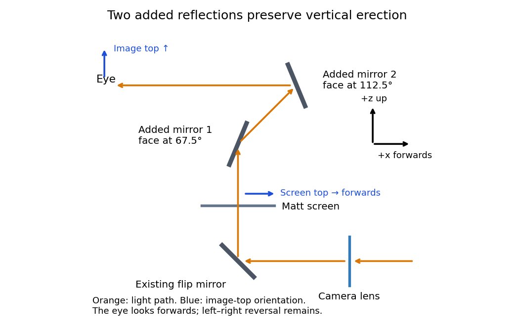
An original vertical-section ray construction with the minimum two added plane mirrors
. Details. 
Use a converging thin lens as a magnifying glass, with the screen at or just inside its front focal plane. It presents an upright virtual image at infinity or at the eye's near point, respectively. Let the near point distance be ; the conventional numerical assumption is , which is not specified in the paper.
Under the usual approximation that the eye is close to the eyepiece, interpreting as the focal length gives the familiar angular magnificationsThe first is for a relaxed eye with the screen at the front focal plane. For the second, the virtual image is at signed distance and the thin lens equation gives screen distance . Thus the often intended maximum requires a screen-to-eye distance of approximately , rather than exactly .
If instead fixes the physical screen-to-eye separation , an eye adjacent to the optical lens sees the angular magnificationThis is achieved by for relaxed viewing, or by for a virtual image at the near point. The latter follows from .
More generally, the source does not specify the eyepiece-to-eye distance either. If that distance is , then and a virtual image at the near point has transverse magnification . Its angular magnification relative to unaided viewing at isFor example, and give , with and . This is a concrete counterexample to a universal maximum of at fixed screen-to-eye separation. In ideal geometrical optics, allows arbitrarily large with an arbitrarily short focal length; practical aperture and optical aberrations constrain this. A unique numerical maximum therefore needs the conventional near-eye eyepiece geometry and near point assumption. The conventional answer is , with those assumptions stated explicitly.
Let be the drop in electric potential along the positive electric charge's path. By conservation of energy, , so the nonrelativistic exit speed is . Apply a uniform magnetic field perpendicular to the incident velocity and to the desired orbital plane. The magnetic Lorentz force is perpendicular to the velocity, does no work, and supplies the centripetal force:For example, and give initial deflection along for positive . Reversing the magnetic field reverses the bending. A uniform electric field alone would give constant acceleration and a parabolic path, not uniform circular motion. The displayed result assumes ; the exact relativistic momentum relation would give .
Add a uniform electric field satisfying . Then the Lorentz force vanishes for the desired velocity. With the axes used above, , perpendicular to both and , withThe crossed fields form a velocity selector. All particles must first have traversed the same electric potential difference from rest: that is what converts selection of speed into selection of charge-to-mass ratio. Equal charge-to-mass ratios yield equal speeds even if the separate masses and charges differ. For other ratios, the initial transverse force is and is nonzero.
Use sinusoidal phasors with physical values , , and . The complex impedance is : its modulus is the voltage-to-current amplitude ratio, and its complex argument is the voltage-minus-current phase difference. Here is the electrical resistance part and the signed electrical reactance; the source's notation differs from the common notation.
The component laws , and give the complex impedances of an ideal resistor, inductor and capacitor:In a series circuit the same electric current flows through both components, so Kirchhoff's voltage law adds their voltage phasors. The resulting series RC impedance isFor positive , the negative phase difference means that electric current leads the applied electric potential difference.
In the parallel LC circuit both components have the same voltage phasor. Adding their current phasors by Kirchhoff's current law gives the total electrical admittance:ThusAt the ideal parallel resonance, , the two branch current phasors cancel. The net electrical admittance is zero and the magnitude of the complex impedance tends to infinity: the parallel combination behaves as an open circuit at that frequency. Its complex argument is undefined exactly at the pole. Finite component losses replace the infinite peak by a large finite electrical impedance. This conclusion concerns a voltage-driven sinusoidal response; an ideal resonant current drive does not have a bounded sinusoidal steady-state voltage.
Articles were limited to the first 100 out of 866 total.
Articles by others on the same topic
There are currently no matching articles.