A lies on the continuation of the offset outside the two ridge tips: it is the fracture zone, whose two sides are carried in the same overall plate direction. A bathymetric step can remain because the two sides have different ages and thermal histories, without continuing plate-boundary strike-slip faulting.
B is the black segment connecting the two white spreading ridges. Construct the plate motion from divergence away from those ridge axes. Between their tips, the upper side of B belongs to the plate west of the right-hand ridge and moves approximately west-northwest; the lower side belongs to the plate east of the left-hand ridge and moves approximately east-southeast. Looking across B from either side, the opposite side moves to the observer's left. B is therefore a left-lateral strike-slip faulting on a transform fault. The offset preserved outside the active segment must not be read as the sense of present slip.
The grey arrows in the source image are pointers to detachment faults, not plate-motion vectors. The original publication identifies white lines as spreading ridges, black lines as transform faults, and arrows as pointers to detachments. Its Figure 1b is the unlettered source of the exam's Figure 3.[ref]
C lies on the white spreading ridge extending down from the left-hand ridge-transform intersection. Relative motion there is extensional, so its tectonic faults have normal slip. Dike intrusion also accommodates extension at a spreading ridge; “normal slip” is the appropriate category among the four offered, not a claim that all spreading is achieved by a single normal fault.
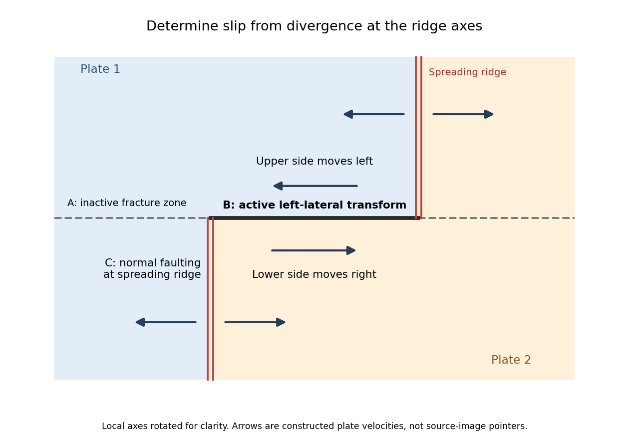
Why the active transform in the supplied geometry is left lateral
. Original idealized plan-view construction using the supplied ridge arrangement and relative motion directions. It illustrates the kinematic test, rather than reproducing the exam bathymetry. Details.
Articles by others on the same topic
There are currently no matching articles.