The lower NMOS transistor network conducts through either the series branch or the series branch. Complete the upper PMOS transistor network by the series-parallel dual: between and an intermediate node put and in parallel, and between that node and put and in parallel. There are four upper transistors, complementing the four lower transistors. Use the usual body ties to the corresponding supply rails. Each denotes a PMOS transistor controlled by input , so it conducts when .
The upper conducting condition is , exactly the complement of . Thus for every stable input the output has a conducting path to exactly one rail in the ideal static CMOS model. The left panel below specifies the added network independently of the source drawing; join its lower terminal to the existing output.
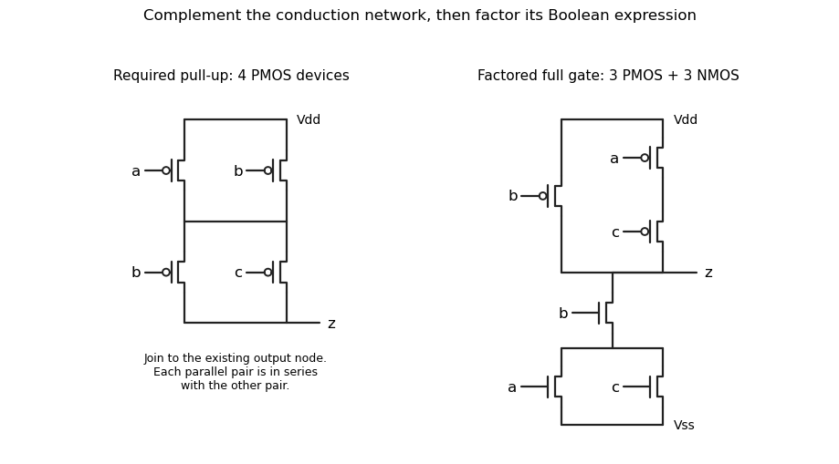
Original solution schematics: the required four-device pull-up network, and a factored six-transistor realization of the same gate. Bubbles identify PMOS gates.
Details. 
Articles by others on the same topic
There are currently no matching articles.