Solutions to all eight questions of the 7 September 2022 resit. Released Oxford examination archive, member
2021/L/a10101w1.pdf. The dated cover establishes the year despite the undated held filename and misleading archive directory. The Thumb instruction set listings assume the 32-bit AAPCS32 data layout; the timer calculation in Question 2 corrects a numerical slip in the paper.Use
r0 for the argument and result. With 32-bit integers and pointers, the three fields have byte offsets 0, 4 and 8. Assume an acyclic finite binary tree, no concurrent mutation, a valid aligned call stack, and no signed integer overflow in any evaluated sum. These are representation and arithmetic assumptions, rather than properties of arbitrary C programming language implementations..syntax unified
.cpu cortex-m0
.thumb
.global sum_rec
.thumb_func
sum_rec:
cmp r0, #0
beq .Lempty
push {r4, r5, r6, lr} @ 16-byte frame; r6 is alignment padding
movs r4, r0 @ retain this invocation's node
ldr r5, [r4, #0] @ running value begins with its label
ldr r0, [r4, #4]
bl sum_rec @ r0 = left subtree sum
adds r5, r5, r0
ldr r0, [r4, #8]
bl sum_rec @ r0 = right subtree sum
adds r0, r0, r5
pop {r4, r5, r6, pc} @ restore caller state and return
.Lempty:
movs r0, #0
bx lrThe node and partial sum are held in callee-saved registers
r4,r5. Each recursive invocation saves its caller's values before replacing them, so a child returns with the parent's values intact. Saving lr preserves the return address across the two bl instructions. Caller-saved registers may be overwritten by a child; no parent value is left live only in them. Pushing four words maintains eight-byte stack alignment at recursive calls.[ref]Procedure Call Standard for the Arm Architecture by ARM Limited. AAPCS32, base standard: core-register roles, stack constraints and result return
Correctness follows by structural induction. An empty subtree returns zero. For a nonempty subtree, assume both recursive calls return their respective label sums. The final addition then combines the node's label with exactly those two sums, so
r0 returns the sum of all labels. The instruction forms and field offsets fit the short load and arithmetic encodings.[ref]Thumb 16-bit instruction set quick reference by Arm. Move, Add, Load, Push/Pop and Branch tables
Use an explicit-stack depth-first tree traversal. Descend the left branch immediately and put each nonempty right subtree on a stack for later. For the same node declarations as in the paper, an original C programming language implementation is:
int sum_iter(tree t)
{
    tree pending[32];
    unsigned top = 0;
    int total = 0;
    while (t != NULL || top != 0) {
        if (t == NULL) {
            t = pending[--top];
        } else {
            total += t->data;
            if (t->right != NULL)
                pending[top++] = t->right;
            t = t->left;
        }
    }
    return total;
}
The loop invariant says that the accumulated labels plus the sums of the current subtree and all pending subtrees equal the original tree sum, with the unvisited subtrees disjoint. Visiting a node adds its label and replaces its subtree by its two children. Popping merely changes which pending subtree is current. When both current and pending subtrees are absent, the invariant proves the result.
At most one unvisited right sibling is pending at each level of the current ancestor path. If depth means the number of nonempty nodes on a longest root-to-leaf path, depth at most 32 requires at most 31 pending right siblings. A 32-word array is therefore sufficient; it also covers the convention that depth counts at most 32 edges. The depth promise makes unchecked pushes valid here. For arbitrary input, a production implementation should check capacity rather than overwrite its frame.
A corresponding Thumb instruction set implementation keeps the total in
r4, the array base in r5, and its next-free address in r6:.global sum_iter_asm
.thumb_func
sum_iter_asm:
push {r4, r5, r6, lr}
sub sp, sp, #128 @ 32 pending pointers
mov r5, sp @ base of pending array
mov r6, sp @ empty stack: next-free equals base
movs r4, #0
.Lvisit:
cmp r0, #0
beq .Ltake_pending
ldr r1, [r0, #0]
adds r4, r4, r1 @ consume this node's label
ldr r1, [r0, #8]
cmp r1, #0
beq .Lleft
str r1, [r6, #0] @ defer the nonempty right subtree
adds r6, r6, #4
.Lleft:
ldr r0, [r0, #4] @ continue down the left branch
b .Lvisit
.Ltake_pending:
cmp r6, r5
beq .Ldone
subs r6, r6, #4
ldr r0, [r6, #0]
b .Lvisit
.Ldone:
movs r0, r4
add sp, sp, #128
pop {r4, r5, r6, pc}The stack pointer stays fixed while the array is used;
r6 is a separate cursor inside that array. All callee-saved registers touched by the function are restored. Each nonempty node contributes its label exactly once. As in part (a), require that every partial total fits the signed result type; a representable final answer alone does not prevent overflow in a different summation order.Let be the number of nonempty nodes and the maximum number on a root-to-leaf path. Both listings take time on a unit-cost machine: each node is visited once and its three fields are read once. The recursive listing executes two child calls per nonempty node, including calls on empty children; there are invocations in total. It saves and restores four words for every nonempty invocation. The iterative listing has one function frame, no recursive calls, and one push/pop pair per deferred nonempty right subtree. Thus it removes repeated call/return and frame-transfer overhead, although its extra loop tests also cost instructions. Exact cycle comparisons need a specified processor, memory timing and compiler; an optimizing compiler may alter either implementation.
For these particular assembly language listings, the recursive call stack uses bytes above the caller's frame; empty calls allocate no additional frame. The iterative listing uses a fixed bytes, even for a shallow or empty tree. With , the recursive maximum is 512 bytes, versus 144 bytes for this fixed-array iteration. If the promised depth of 32 instead counts edges, the recursive bound is bytes; the same 32-word pending array still suffices. Conversely, for recursion uses at most 128 bytes and is smaller than the fixed array. When sized dynamically to depth, both approaches use auxiliary storage, but their stored information differs: full suspended invocation state versus pending subtree roots. Therefore recursion is not intrinsically always slower or larger; the claim depends on generated code, tree shape and the choice to reserve a maximum-size explicit array.
Keep successive timestamps in raw unsigned ticks, and convert their modular difference to milliseconds only after subtraction. The first pulse establishes a timestamp; it does not create a fictitious interval from startup. Store valid intervals in a five-element ring buffer. During startup, average the one to four intervals actually available; return zero until there is at least one valid interval. Here zero is explicitly an unavailable-data sentinel.
The following C programming language code uses the supplied register names through an abstract memory-mapped input-output register interface. The board port supplies the actual register mapping and interrupt vector; no undocumented addresses are assumed. The two interrupt-mask hooks have the exact semantics described below and are interface requirements, not names asserted to exist in an unspecified device library.
#include <stdint.h>
#include <stdbool.h>

struct gpio_registers { volatile uint32_t EVENT; };
struct timer_registers { volatile uint32_t COUNT; };
extern struct gpio_registers GPIO;
extern struct timer_registers TIMER;

uint32_t irq_save_disable(void);
void irq_restore(uint32_t old_mask);

static volatile uint32_t interval_ms[5];
static volatile uint32_t next_slot = 0;
static volatile uint32_t valid = 0;
static volatile uint32_t previous_tick = 0;
static volatile bool have_previous = false;

void gpio_handler(void)
{
    if (GPIO.EVENT == 0)
        return;
    uint32_t now = TIMER.COUNT;
    GPIO.EVENT = 0;                 /* acknowledge with the specified write */
    if (have_previous) {
        uint32_t ticks = now - previous_tick;
        interval_ms[next_slot] = ticks / UINT32_C(16000);
        next_slot = (next_slot + 1) % 5;
        if (valid < 5)
            ++valid;
    } else {
        have_previous = true;
    }
    previous_tick = now;
}

uint32_t get_pulse(void)
{
    uint32_t local[5];
    uint32_t mask = irq_save_disable();
    uint32_t n = valid;
    for (uint32_t i = 0; i < n; ++i)
        local[i] = interval_ms[i];
    irq_restore(mask);             /* restore the earlier mask, not just enable */

    if (n == 0)
        return 0;
    uint64_t total = 0;
    for (uint32_t i = 0; i < n; ++i)
        total += local[i];
    if (total == 0)
        return 0;
    /* Mean duration is total/n milliseconds; round bpm to nearest integer. */
    return (uint32_t)((UINT64_C(60000) * n + total / 2) / total);
}
Before the buffer fills, its valid entries occupy positions . Once full, all five positions are valid, so their order is irrelevant to their sum. The conversion uses 16,000 ticks per millisecond. Truncating each interval introduces less than one millisecond of error per interval. The desired conversion is beats per minute, the reciprocal of the mean interval; averaging the individual values is generally different.
irq_save_disable saves the previous interrupt mask and prevents the GPIO handler from running until irq_restore restores that mask. Both hooks must include compiler memory barriers. On an appropriate privileged Cortex-M target, the implementation can use MRS PRIMASK, CPSID i and MSR PRIMASK, with a compiler memory clobber. These target operations implement interrupt masking; they are not expressible as portable ISO C alone. One concrete GCC/Clang-compatible privileged Cortex-M port for those hooks is:uint32_t irq_save_disable(void)
{
uint32_t old_mask;
__asm__ volatile ("mrs %0, primask\n\tcpsid i"
: "=r" (old_mask) : : "memory");
return old_mask;
}
void irq_restore(uint32_t old_mask)
{
__asm__ volatile ("msr primask, %0"
: : "r" (old_mask) : "memory");
}The compiler memory clobbers prevent access motion across the mask changes. Saving and restoring the entire prior mask is intentional; an unconditional enable would break an enclosing critical section.[ref]
CMSIS-Core register access documentation by Arm. PRIMASK, __get_PRIMASK, __disable_irq and __set_PRIMASK
All state is initialized before enabling the peripheral interrupt. Assume the timer read is coherent, the handler is not reentered, and the device follows the stated write-zero acknowledgment semantics.
The interrupt handler is the only writer of
interval_ms, valid and next_slot. The foreground function takes an interrupt-safe ring-buffer snapshot inside a short critical section, copying the count and exactly that many valid entries before restoring the previous mask. It performs the comparatively expensive summation and division after interrupts are restored. A new pulse then affects the next query, while the current query consistently describes the earlier snapshot.Without exclusion, the foreground could read an old entry, be interrupted while the buffer is updated, then read new entries or an inconsistent count. Even indivisible 32-bit loads would not make that multi-element snapshot atomic. The volatile-qualified objects in C ensure that the compiler performs required shared or device accesses;
volatile does not provide mutual exclusion or a coherent multiword snapshot.[ref]C11 committee draft N1570. Sections 5.1.2.3 and 6.7.3, observable volatile accesses and type qualifiers
This design assumes a single-core foreground/interrupt execution model: no other interrupt, DMA engine or core modifies the protected buffer. The mask hooks must prevent compiler reordering across their boundaries and really mask the GPIO interrupt. Restoring the saved mask also makes the function safe to call when interrupts were already disabled. Keep the critical section short enough that the event register does not coalesce multiple heartbeats while interrupts are masked; otherwise the hardware interface cannot reconstruct events it never recorded.
A 32-bit free-running timer operates modulo . If its previous reading is , and the actual elapsed count is with , the new reading is . The modulo-counter elapsed-time identity therefore givesUnsigned integer arithmetic in C reduces the subtraction modulo , so the identity remains valid when a wrap occurs between pulses. For example, readings and give 16,000 ticks, hence one millisecond, rather than a negative interval.[ref]
C11 committee draft N1570. Section 6.2.5 paragraph 9, unsigned arithmetic modulo one greater than the maximum representable value
At the specified clock rate, the true wrap period is seconds. The printed 256 seconds is inconsistent with the other two specifications. The implementation uses the stated 32-bit width and 16 MHz rate. Assuming consecutive handled pulses are less than 256 seconds apart is a sufficient conservative bound; the exact allowable bound is less than 268.435456 seconds.
This calculation requires less than one entire timer modulus of elapsed ticks between successive stored timestamps. If a whole wrap or several wraps elapse, identical register readings cannot reveal how many occurred; an overflow counter or an independent longer-range clock would be needed. Also assume pulse events are not lost and interrupt latency is constant or sufficiently small for the required accuracy: timestamps read in software measure handler-to-handler intervals, not perfect hardware capture times. Conversion to milliseconds occurs after modular subtraction, so separately rounded absolute timestamps cannot corrupt the wrap calculation.
The lower NMOS transistor network conducts through either the series branch or the series branch. Complete the upper PMOS transistor network by the series-parallel dual: between and an intermediate node put and in parallel, and between that node and put and in parallel. There are four upper transistors, complementing the four lower transistors. Use the usual body ties to the corresponding supply rails. Each denotes a PMOS transistor controlled by input , so it conducts when .
The upper conducting condition is , exactly the complement of . Thus for every stable input the output has a conducting path to exactly one rail in the ideal static CMOS model. The left panel below specifies the added network independently of the source drawing; join its lower terminal to the existing output.
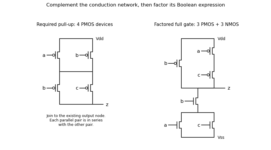
Original solution schematics: the required four-device pull-up network, and a factored six-transistor realization of the same gate. Bubbles identify PMOS gates.
Details. 
The pull-down Boolean function is . A conducting pull-down makes , soIn particular, if the output is always high; if , the output is high precisely when both other inputs are low. These cases give the truth table without confusing a network's conducting condition with the output voltage.
Factor the common input before constructing the networks. Use an NMOS transistor controlled by in series with parallel NMOS transistors controlled by and . Its conducting condition remains . The complementary upper network is a PMOS transistor controlled by in parallel with a series chain of PMOS transistors controlled by and ; its conducting condition is .
This is the right panel in part (a). It uses three lower plus three upper transistors, six in total instead of eight, and needs no separate inverter or complemented external input. The complementary CMOS network duality ensures the same static Boolean function and complementary rail connections.
Use a synchronous sequential circuit with four Moore machine states. is ready, is the one-cycle pulse state, is disabled with no qualifying final zero, and is disabled after one sampled zero. Reset into , so an initial sampled high generates a pulse immediately. The complete transition/output table is:
| State | Code | Next if | Next if | |
|---|---|---|---|---|
A particularly small implementation uses two D flip-flops with the next-state equationsBoth D flip-flops share the clock; their outputs feed the displayed logic gates. The output depends only on the stored state, not combinationally on the external input. At each edge, evaluate the right-hand sides using the old state and the sampled input, then update both flip-flops together. The resulting applies throughout the following clock period.
From , a high enters . The next edge always leaves , so the pulse lasts exactly one period. In the disabled states, a high leads to and erases progress towards rearming. A zero enters , and a second successive zero enters . A later high can then enter . This proves both the two-zero requirement and the startup exception. For example, sampled inputs yield outputs .
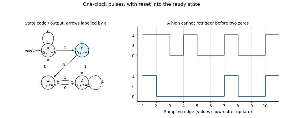
Original Moore-state design and clocked example for the two-zero rearming pulse detector. State and output are shown after each sampling edge.
Details. 
The construction is a synchronous pulse detector with two-zero rearming. Assume meets setup/hold requirements at the sampling edges. A genuinely asynchronous input would first require synchronization, with its associated latency; that is separate from this sampled-input specification.
The update must place the sum of the two current entries in the first coordinate and retain the old first coordinate in the second. Thus choose the matrixBy matrix multiplication, for every , using the given recurrence relation. This is the companion-matrix representation of the Lucas numbers.
Use mathematical induction on . For , the identity matrix gives . If , applying and using part (a) gives . ThereforeThe base case is essential: the starting vector represents consecutive Lucas numbers, not two arbitrary initial values.
The characteristic polynomial isIts two distinct real roots are the eigenvaluesTheir product is , so . Equivalently, implies . The positive eigenvalue is the golden ratio.
For an eigenvalue , the equation gives and . The second identity holds because . Taking gives the eigenvectorsEach associated eigenspace consists of all scalar multiples of its displayed vector. A zero vector is excluded when speaking of an eigenvector.
The requested order is . To obtain this order directly, put the transposes of the two eigenvectors in the rows of , using the fact that is symmetric:Then , so is an invertible matrix, withMultiplication gives , since and . Multiplying by proves the required diagonalization. Putting the eigenvectors in columns would instead give the equally standard order , so the convention must be checked rather than copied mechanically.
The initial vector decomposes especially simply in the eigenbasis:because . Applying multiplies the two eigenvectors by and . Part (b) then yieldsReading the second coordinate gives the Lucas closed formAt this is 2 and at it is 1. Each summand obeys the same recurrence relation, which independently verifies the formula and explains why the irrational parts cancel to give an integer.
Rearrange the identity intoTaking determinants gives . Hence , so is an invertible matrix, with . This uses that the matrices are finite and square: a right inverse then implies a two-sided inverse. Applying the identity to a vector in the kernel without first establishing commutation would not justify cancelling an on the wrong side. The argument is a case of invertibility forced by a polynomial product identity.
Multiply the original equation on the left by to obtainEach term on the right commutes with . ThusNo general commutativity of matrix multiplication is being assumed; it follows from this particular expression for .
Let for a real eigenvalue and a nonzero real eigenvector . Part (b) gives and . The expression for in part (c) therefore givesConsequently is a real eigenvalue of , with the same eigenvector . For a real matrix and real eigenvalue, a nonzero real vector can be chosen in the real kernel of ; no complex-vector assumption is needed.
For scalar , part (c) givesThe numerator is strictly positive for every real , and the denominator is nonzero. Therefore and hence is invertible. This proof uses the order structure of the real scalars; it does not say that the matrix must be nonsingular in higher dimension.
An integer-entry example isDirect matrix multiplication gives , so adding and gives the zero matrix. Equivalently, this is the companion matrix of and has the two nonreal cube roots of unity as eigenvalues. The direct multiplication is already a complete proof. It also shows why part (e) does not extend to all real square matrices: with this , choosing satisfies the original product identity.
For , the all-ones matrix is , so and whenever . These subspaces have dimensions one and two and span . Thus the eigenvalues are and .
The eigenspace for 3 has basis . The eigenspace for 0 is the plane , with basisThe last two vectors are linearly independent and every vector in the plane equals .
Assume . With , the all-ones matrix satisfies . Hence is an eigenvalue, and for the other eigenvalue is . At the matrix is , so 1 is its only eigenvalue; zero is not an eigenvalue with a nonzero eigenvector in that case.
A basis of is . For ,The displayed vectors are linearly independent by their first coordinates, and every vector with zero coordinate sum has exactly that expansion. At this list is empty and the kernel is ; it is not an additional eigenspace associated with a present eigenvalue. This is the spectrum of an all-ones matrix.
The decomposition into and the zero-sum vector subspace gives characteristic polynomial . For , has algebraic multiplicity and geometric multiplicity one; zero has both multiplicities . At , only the eigenvalue 1 occurs, with both multiplicities one. Referring to a multiplicity zero for the absent root zero is merely a bookkeeping convention, not an assertion that it is an eigenvalue.
The all-ones matrix is diagonalizable for every . The vector together with the vectors from part (ii) is an eigenbasis. Independence follows because a multiple of has coordinate sum times that multiple, whereas every other basis vector has coordinate sum zero. In this basis the diagonal matrix is . At the one-vector basis suffices. Alternatively, the spectral theorem for real symmetric matrices applies. If dimension zero is allowed by the convention for , the empty matrix has no eigenvalues, an empty basis and a vacuous diagonalization.
If with , put . The matrix geometric series telescopes on both sides:Thus is nonsingular, andThis is a finite polynomial identity for a nilpotent matrix; no convergence argument or bound is required.
Write with a diagonal matrix. Then , so each diagonal entry satisfies and therefore . Hence and . Conversely the zero matrix is diagonalizable and nilpotent. This proves the existing result that a diagonalizable nilpotent matrix is zero; nilpotence alone does not imply a zero matrix, because nonzero nilpotent Jordan blocks exist.
Reading the abstract syntax tree recursively gives the eight distinct subformulasA subformula includes the complete propositional formula itself as well as the operands of its connectives. There are nine occurrences in the abstract syntax tree, because the atomic formula occurs twice, but only eight different propositional formulas in the set.
Eliminate the logical implication and apply De Morgan's laws:This is disjunctive normal form: a logical disjunction of conjunctions of literals. It has four literal occurrences, namely , meeting the stated bound.
Repeated use of yieldsThis logical disjunction is false exactly when are all true and is false. There is precisely one such Boolean valuation out of the assignments to the independent propositional variables. Thus the number of satisfying assignments is . This is the satisfying-assignment count for nested implications; the implication brackets associate to the right here.
Simultaneous propositional substitution givesLet . The first disjunct equals . By De Morgan's laws, implies , so absorption reduces that first disjunct to . The second disjunct is and is also absorbed by . ThereforeThe resulting Boolean function is false only when both and are true, providing a four-row truth table check.
Assume the logical conjunction temporarily, then eliminate the premise's logical disjunction by cases. A natural deduction proof, with each indented assumption delimiting its own subproof, is:
1.  not P or not Q                    premise
2.  | P and Q                        temporary assumption
3.  | P                              and-elim-L, 2
4.  | Q                              and-elim-R, 2
5.  | | not P                        first disjunction case
6.  | | false                        not-elim, 3,5
7.  | | not Q                        second disjunction case
8.  | | false                        not-elim, 4,7
9.  | false                          or-elim, 1, cases 5-6 and 7-8
10. not (P and Q)                     not-intro, discharge 2-9
Lines 5–6 and 7–8 are separate sibling subproofs, not one nested inside the other. Both derive the same contradiction under the common assumption on line 2. Logical disjunction elimination discharges the two case assumptions, and negation introduction then discharges the logical conjunction assumption. The sole undischarged premise is the required one. This proof uses only the supplied logical conjunction, logical disjunction and negation rules; no converse form of De Morgan's laws is being assumed as an extra rule.
Using first-order logic with equality, one suitable sentence isThe distinct witnesses give at least two solutions, and the universal clause excludes every third solution. All variables are bound, and the same equation variable is used in every solution predicate. This is an instance of a first-order definition of exactly finitely many witnesses.
On the universe , interpret the first-order signature byThis assigns both constants, a total binary function, a unary relation and a binary relation, so it specifies a complete first-order structure. If and both hold, then , and hence , proving the consequent. If either premise fails, the implication is true. Thus the universally quantified implication holds for every pair of integers, nonvacuously for every pair of nonnegative integers. Distinct constant symbols need not denote distinct objects unless a separate axiom requires it.
Describe a branching vertex by the first-order logic sentenceand the existence of a sink by . The directed path has sinks but no branching vertex; the directed cycle has neither sinks nor branching vertices; the directed arborescence has a branching vertex. Thus the following three sentences distinguish the named structures in order:Here are abbreviations for the displayed formulas; replacing them gives sentences in the single-relation first-order signature . Explicitly, says that some vertex has no successor and that no vertex has two distinct successors. The truth table across the three structures is:
| Sentence | |||
|---|---|---|---|
The conditions distinguish these three finite structures; they are not claimed to characterize all directed paths, cycles or trees among arbitrary directed graphs. Only local out-degrees and the presence of a sink are needed, without quantifying over paths of unbounded length.
The occurrence of in lies under the quantifier . Directly inserting the term would capture its free : the result would make the inserted bound and change the intended dependence on the original free value. Therefore the term is not free for the literal substitution requested.
Perform capture-avoiding first-order substitution by first renaming bound variables to fresh names. Renaming the first binder to is necessary; renaming the second to is optional but makes the result especially clear. These renamings give the equivalent formula . Substituting only the free occurrences of now givesBoth and in the inserted term remain free variables. The original has scope only over its own disjunct and would not capture the inserted in the first disjunct; its optional renaming is not a necessary capture repair. This distinction avoids confusing reuse of a letter elsewhere with binding within the relevant scope.
First negate the implication, then move the negation through the existential quantifier and the logical conjunction:This is negation normal form, because each negation is immediately in front of an atomic predicate. The occurrence of remains free. Keeping also avoids assuming any additional order axioms for the relation symbol ; if it has its usual linear-order interpretation, that atom can instead be expressed as .
Articles by others on the same topic
There are currently no matching articles.