The lower NMOS transistor network conducts through either the series branch or the series branch. Complete the upper PMOS transistor network by the series-parallel dual: between and an intermediate node put and in parallel, and between that node and put and in parallel. There are four upper transistors, complementing the four lower transistors. Use the usual body ties to the corresponding supply rails. Each denotes a PMOS transistor controlled by input , so it conducts when .
The upper conducting condition is , exactly the complement of . Thus for every stable input the output has a conducting path to exactly one rail in the ideal static CMOS model. The left panel below specifies the added network independently of the source drawing; join its lower terminal to the existing output.
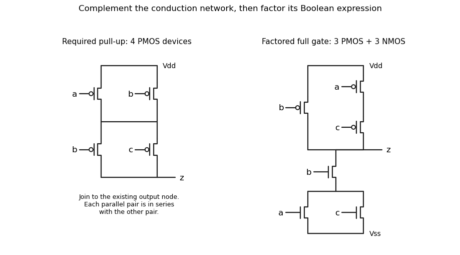
Original solution schematics: the required four-device pull-up network, and a factored six-transistor realization of the same gate. Bubbles identify PMOS gates.
Details. 
The pull-down Boolean function is . A conducting pull-down makes , soIn particular, if the output is always high; if , the output is high precisely when both other inputs are low. These cases give the truth table without confusing a network's conducting condition with the output voltage.
Factor the common input before constructing the networks. Use an NMOS transistor controlled by in series with parallel NMOS transistors controlled by and . Its conducting condition remains . The complementary upper network is a PMOS transistor controlled by in parallel with a series chain of PMOS transistors controlled by and ; its conducting condition is .
This is the right panel in part (a). It uses three lower plus three upper transistors, six in total instead of eight, and needs no separate inverter or complemented external input. The complementary CMOS network duality ensures the same static Boolean function and complementary rail connections.
Use a synchronous sequential circuit with four Moore machine states. is ready, is the one-cycle pulse state, is disabled with no qualifying final zero, and is disabled after one sampled zero. Reset into , so an initial sampled high generates a pulse immediately. The complete transition/output table is:
| State | Code | Next if | Next if | |
|---|---|---|---|---|
A particularly small implementation uses two D flip-flops with the next-state equationsBoth D flip-flops share the clock; their outputs feed the displayed logic gates. The output depends only on the stored state, not combinationally on the external input. At each edge, evaluate the right-hand sides using the old state and the sampled input, then update both flip-flops together. The resulting applies throughout the following clock period.
From , a high enters . The next edge always leaves , so the pulse lasts exactly one period. In the disabled states, a high leads to and erases progress towards rearming. A zero enters , and a second successive zero enters . A later high can then enter . This proves both the two-zero requirement and the startup exception. For example, sampled inputs yield outputs .
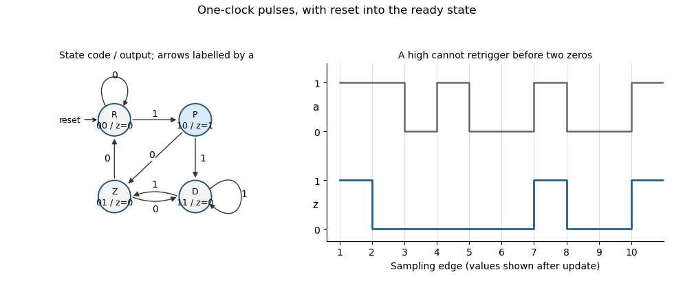
Original Moore-state design and clocked example for the two-zero rearming pulse detector. State and output are shown after each sampling edge.
Details. 
The construction is a synchronous pulse detector with two-zero rearming. Assume meets setup/hold requirements at the sampling edges. A genuinely asynchronous input would first require synchronization, with its associated latency; that is separate from this sampled-input specification.
Articles by others on the same topic
There are currently no matching articles.