A displaced drainage forms when repeated horizontal fault slip offsets a channel and its upstream and downstream reaches no longer line up. In plan view, draw two initially continuous channel reaches crossing the fault, translate one side parallel to the fault strike, and connect the reaches by a short fault-parallel reach. A linear valley develops where erosion follows damaged rock along a straight fault zone.
In Attachment A, use the oblique, relatively straight valley running southwest–northeast through the lower centre towards the upper right. For an identifiable example, follow the central approximately north–south drainage to its bend near the southern edge of the central basin, about , where is fraction from the left image edge and fraction from the top. Mark its deflected reach and the adjacent straight valley. The positional precision is at the level of the supplied image; establishing a numerical fault offset would require correlated piercing points and field checks.
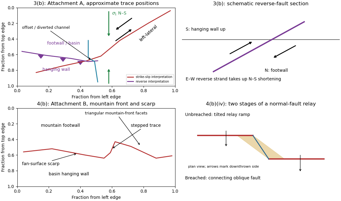
Original interpretive sketches for Attachments A and B, with normalized image positions and a normal-fault relay
. Details. 
A reverse fault can create a sharp mountain front by raising its hanging wall beside a lower footwall. Drainages entering the rising block may be deflected along the front or cut narrow gorges across it. In cross-section, draw a dipping fault with the hanging wall displaced up-dip and a surface-height contrast above the trace.
In Attachment A, mark the approximately east–west to west-northwest–east-southeast break between the southwestern mountain block and the central basin. Its approximate image coordinates run from through and to . The abrupt topographic change and diversion of drainage along this front support the reverse faulting interpretation. It is the southern margin of the central basin, not the much straighter oblique valley farther northeast. The original interpretive figure gives a schematic section.
Trace the strike-slip fault along the southwest–northeast valley, approximately through . The long oblique strand is interpreted as left-lateral strike-slip faulting: draw the southeastern side moving northeast and the northwestern side moving southwest, parallel to the trace.
This sense is consistent with horizontal north–south maximum compression: for an approximately northeast-striking fault, the resolved shear stress moves the southeastern side northeastward relative to the northwestern side. The deflected central drainage supports that interpretation. The regional stress direction supplies a consistency check rather than a uniquely precise trace location; follow the geomorphic break rather than drawing a single straight line through every coordinate.
Put the reverse fault along the mountain-front trace identified in part (ii), with the mountainous southern/southwestern block as hanging wall and the central basin to its north/northeast as footwall. Draw teeth on the southern hanging wall side of the line. In the simplest cross-section the fault dips south and the southern block moves northward and up over the basin edge. The image constrains the surface trace and relative uplift more securely than its subsurface fault dip; the precise dip cannot be measured from this map alone.
The network partitions deformation into oblique horizontal displacement on the strike-slip fault and more directly north–south crustal shortening on the approximately east–west reverse fault. On the oblique strand, northeastward motion of the southeastern side relative to the northwestern side has a northward component, reducing separation in the direction of . On the reverse fault, northward and upward motion of the southern hanging wall shortens and thickens the crust.
Sketch north–south opposing compression arrows around the plan view, left-lateral arrows along the oblique trace, and teeth on the southern side of the reverse fault trace. A section normal to the latter shows horizontal shortening converted into tectonic uplift. Where strands meet, folding, distributed strain or subsidiary faulting can maintain displacement compatibility; a strike-slip fault terminating abruptly in undeforming rock would not. This is an interpretation involving transpression, and the map does not by itself give a unique partition of slip rates between the strands.
Articles by others on the same topic
There are currently no matching articles.