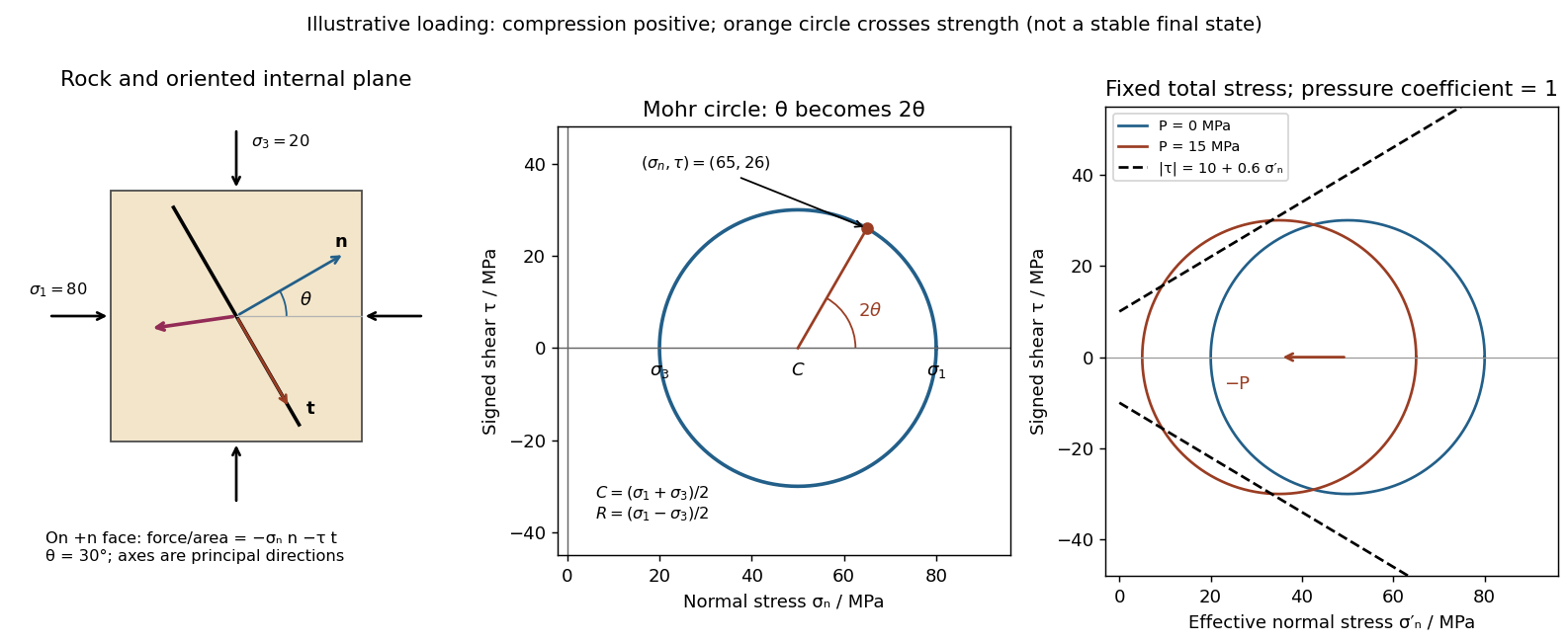
Use compression-positive principal stresses . The two-dimensional Mohr's circle shown is the – circle: its horizontal axis is compressive normal stress , its vertical axis signed shear stress , its centre is , and its radius is . The intercepts and represent principal stress planes, on which shear stress vanishes. The top and bottom points have , the maximum shear stress.
In the rock sketch, is the counterclockwise angle from the direction to the plane's unit normal vector . Choose the clockwise unit tangent and define , with compression positive. Thus a positive produces a positive rotation on the plotted circle. The actual traction on the positive-normal face is . Reversing the tangent convention reverses the plotted shear sign, not the physical prediction.
Stressed rock, Mohr circle, and the effect of pore pressure
. Original illustrative construction with principal compressions 80 and 20 MPa and a plane normal 30 degrees from the maximum compression. The circle point is approximately (65,26) MPa at twice that angle. A separate panel translates the circle left by 15 MPa pore pressure at fixed total stress, bringing it to a frictional failure envelope. Details.
In three dimensions there are circles for each pair of principal stresses. The largest is the – circle; a general three-dimensional plane requires all three principal stresses and its normal, rather than a single angle on this circle.
For a plane whose normal lies in the – plane, rotate through from in the stated sign convention. The circle point givesThe normal-to-plane angle is essential: if the angle supplied is between the plane itself and , use its complement for . The principal stress planes have zero shear stress, and planes at to those principal stress planes have maximum .
For an arbitrary plane in a fully three-dimensional stress field, let be its direction cosines in the principal stress basis. ThenThese follow by resolving the traction into its normal and tangential components; the compression-positive tensor is the negative of the usual tension-positive Cauchy stress tensor. The family of Mohr circles visualizes the possible combinations, but the two-dimensional rule alone does not specify an arbitrary three-dimensional orientation.[ref]
Draw a failure envelope in the plane. A useful brittle shear-failure approximation is the Mohr-Coulomb failure criterionwhere is cohesion, the internal friction angle, and the effective compressive normal stress. A circle wholly inside the envelope is below this ideal failure threshold. Increasing the differential stress expands it until it first touches the envelope: the tangent points identify the failing plane orientations. For a linear envelope, tangency impliesWith the angle convention above, the upper tangent point is at . Its plane therefore makes with the maximum-compression direction; there is a conjugate plane on the other side. For , this is , rather than the plane of maximum shear stress. An existing weak fault can reactivate first, with its own lower cohesion and friction, and need not have this optimum new-fracture orientation.
For tensile brittle fracture, add a tensile strength cutoff: failure occurs when , where . The opening fracture is approximately perpendicular to the minimum-compression direction. Real rock envelopes curve, especially at small confinement; a straight shear envelope must not be extrapolated as an exact tensile law. High confinement can instead favor distributed or ductile deformation, so merely drawing a larger circle does not establish that brittle failure is the active mechanism.[ref]
Stress and strength lecture notes by MIT OpenCourseWare. Lecture 10, frictional strength and Mohr construction; the tensile cutoff is a separate condition.
Pore fluid pressure reduces the compressive load carried across grain contacts or an accessible fault. In the usual elementary approximation,At fixed total stress, increasing translates the entire Mohr circle left by without changing its radius or the differential stress. The circle therefore approaches the frictional failure envelope even though the applied shear has not increased. Equivalently, in total-stress coordinates the strength on an existing plane is , reduced by . For a known orientation and constant frictional parameters, the ideal critical pressure isprovided the plane is in contact and sliding failure is reached before tensile opening.
For the diagram's illustrative , , and , the dry circle is below failure. The freely oriented tangency threshold is about ; the circle is already beyond that threshold and shows the loading tendency, not a stable post-failure state. If grows enough that , fluid pressure can instead open a tensile fracture. A porous-continuum effective stress law may use with a coefficient different from one. Also, changing fluid pressure can change total stress through constrained deformation; pure horizontal translation assumes those total stresses remain fixed.[ref]
Stress and strength lecture notes by MIT OpenCourseWare. Lecture 10, frictional strength modified by pore-fluid pressure.
Articles by others on the same topic
There are currently no matching articles.