
evaporation transfers water to a vapour stream and retains mainly nonvolatile solutes in a concentrate. It can give substantial volume reduction and works across many dissolved-solute compositions. Its disadvantages are heat demand, scaling and corrosion; aerosols, entrainment or volatile radioactive species can contaminate the condensate. Condensate must therefore be sampled or monitored rather than assumed releasable, while the concentrate requires radioactive waste conditioning. A demister limits droplet carryover but does not remove a genuinely volatile contaminant.
ion exchange transfers dissolved radioactive ions to an exchanger, often an ion-exchange resin. It is useful for polishing relatively dilute aqueous streams and can provide selective removal without evaporating the bulk water. Competing inactive ions consume capacity, suspended particles foul the bed, and a neutral or poorly retained species may pass through. Breakthrough measurements determine when the exchanger ceases to meet its target; exhausted resin or regeneration liquors become secondary radioactive waste. Separation performance must be established for the actual feed chemistry, not inferred from the name of the radionuclide alone.
Chemical precipitation with solid–liquid separation uses precipitation, coprecipitation and adsorption to carry contaminants into solids, followed by settling or filtration. It can treat substantial volumes and complex feeds at moderate equipment cost. Its disadvantages are a relatively bulky sludge, incomplete removal of soluble species, and sensitivity to pH, complexation and competing ions. The sludge must be dewatered and conditioned, and the clarified liquid checked for residual radioactive activity. Polishing by another method may still be needed.
In each case, measure both the treated stream and the residue so that the radioactive inventory balance can be checked. Treatment transfers or concentrates radioactive activity; only radioactive decay reduces the number of radioactive parent nuclei. These methods and the distinction between treatment and conditioning are set out in the institutional waste-management framework.[ref]
The useful mechanism is radioactive decay during retention, not chemical destruction of carbon dioxide. With the time in seconds,Here is a radioactive activity concentration; the supplied units are per volume rather than per mass. The original plot follows this concentration over four hours.
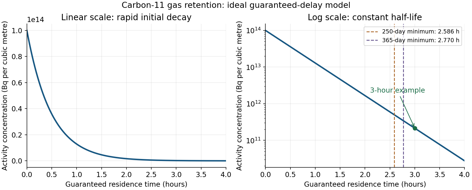

A practical illustrative choice is a three-hour guaranteed residence time, at which , giving about a factor reduction. On a plug-flow basis, the carbon-dioxide-equivalent hold-up volume isUse a contained delay line or a validated retention arrangement that prevents early breakthrough, followed by monitored discharge. A retention bed could instead hold the radioactive carbon dioxide, but its capacity and breakthrough performance would have to be established. Gas retention and monitored discharge are waste-treatment functions, independent of the eventual use of the isotope.[ref]
Predisposal Management of Radioactive Waste from Nuclear Power Plants and Research Reactors by the International Atomic Energy Agency. SSG-40, section 6, gaseous-waste treatment and selection of decay devices
The L result is a flow-delay volume, not a fill-and-immediately-dump tank specification. It credits radioactive decay during the guaranteed transit time and no subsequent storage after discharge from the delay system. Gas entering a filling tank near the end of filling has not aged for the entire filling time. For a literal tank filled for and immediately emptied, the radioactive activity at emptying is insteadThat alternative must not be analysed by multiplying the whole collected inventory by . If “no post filling radioactive decay” is intended to prescribe this literal fill-and-dump arrangement, the three-hour calculation does not establish compliance for it.
The nitrogen fraction is also unspecified. If is the carbon dioxide volume fraction at the stated volume reference conditions, a gas delay line requires , not necessarily L of physical vessel volume. The graph alone does not define a unique optimum: a cost objective, operating calendar and residence-time model are needed. Parts (c) and (d) quantify the discharge constraint for the stated guaranteed-delay design.