Electrical substitution radiometer
ID: electrical-substitution-radiometer

An electrical substitution radiometer measures radiant flux by replacing absorbed optical power with calibrated Joule heating. At fixed temperature, feedback control holds the receiver equally warm with the beam blocked or admitted: after corrections, absorbed optical power equals the reduction in supplied electrical heating. Incident radiant flux additionally requires radiometric absorptance and entrance-path corrections. This connects radiometry to electrical standards.[ref]
Spectroradiometric Detector Measurements: Ultraviolet, Visible, and Near-Infrared Detectors for Spectral Power by Thomas C. Larason and others. §5.2, printed p. 30: electrical substitution and electrical standards
Picture a small absorbing cavity connected to a colder reference block by a radiometer thermal link. A heater supplies Joule heating, a thermometer senses the receiver, and feedback control adjusts the heater. When light supplies some of the heating, the controller supplies less. The readout is the change in heater power, rather than the beam's brightness or its number of photons. NIST's institutional description gives a concrete receiver with a conical interior, absorbing coating and weak Kapton support, operated with a receiver heater and thermometer.[ref]
Pico-Watt ACR by National Institute of Standards and Technology. Description, Design Parameters for Improved ACR Sensitivity; Key Design Features: conical receiver, coating, constant-temperature loop and thin-walled Kapton link
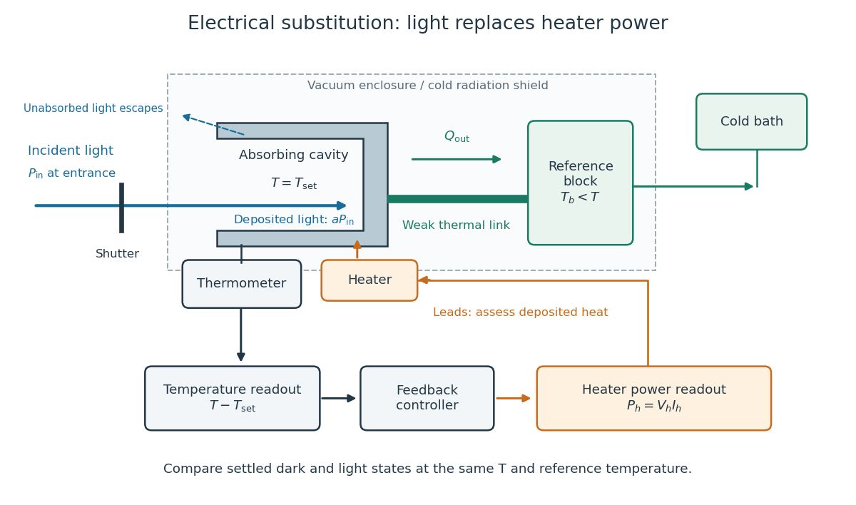
Cavity, radiometer thermal link and heater readout in an electrical substitution radiometer
. Original functional schematic, not a drawing of a particular laboratory instrument. The shutter defines dark and illuminated states; incident radiant flux is specified at the receiver entrance. The cavity absorbs a fraction , while the remainder escapes. The reference block and receiver have distinct controlled temperatures. The thermometer signal drives feedback control, and heater voltage and electric current provide the electrical power readout. Lead heating, stray radiation and spatial heating differences require separate checks. Details.
New to topics? Read the docs here!