Solution
ID: past-exam-of-the-physics-2-paper-of-the-university-of-oxford/2016/11/ii/solution
Past exam of the physics 2 paper of the University of Oxford 2016 11 ii Solution by  Codex 0 2026-10-25
The source's variable inductor and variable resistor are in parallel. Let their combined complex impedance beUse the left and right source terminals as the drive nodes. The upper divider has arms and ; the lower divider has arms and . At bridge balance, the detector draws no electric current and the divider midpoint electric potential differences agree, soSubstitution and cancellation at a nonzero drive frequency giveEquating real and imaginary parts yieldsThe first expression has units of resistance and the second units of inductance. Both are independent of the drive amplitude and, for ideal frequency-independent components, of the chosen nonzero drive frequency. At zero frequency the ideal inductors short their arms and the cancellation would not be valid as a measurement of .
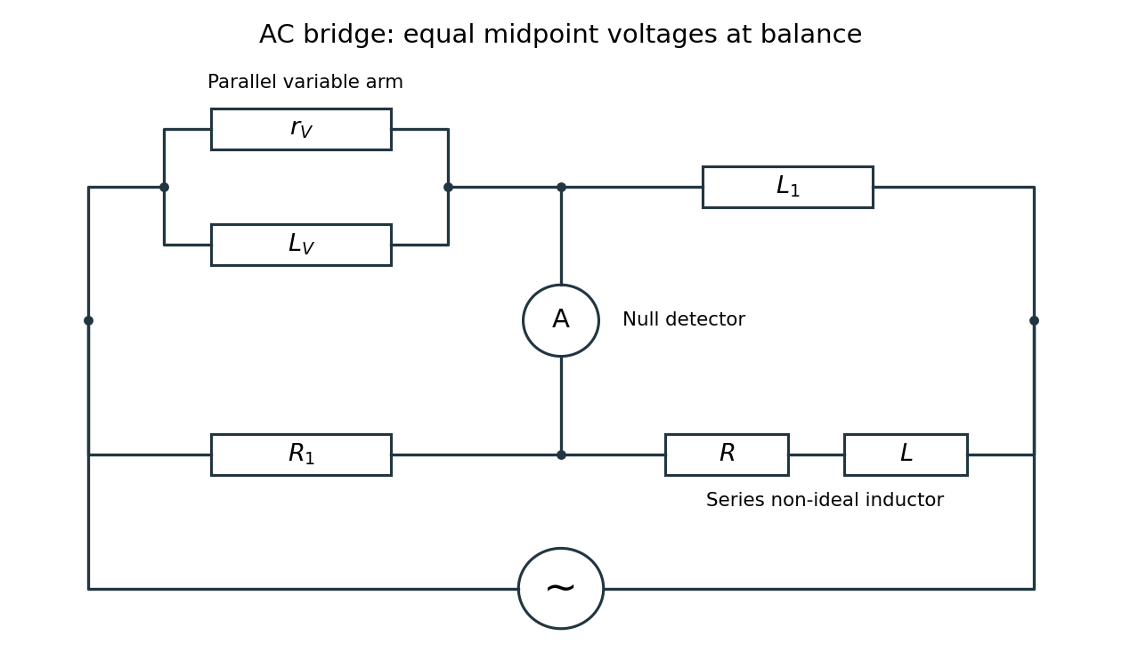

Two applications are precision comparison of an unknown electrical resistance with calibrated standards in a Wheatstone bridge, and detecting small resistance changes in a strain gauge or resistance thermometer. Alternating-current bridges additionally compare capacitance, inductance and dielectric losses; this particular bridge determines the two parameters of a non-ideal inductor from a null measurement.
New to topics? Read the docs here!