Inductance relates electric currents to the magnetic flux linkage they produce. For a single linear coil with fixed geometry and magnetic response, its self-inductance is the constant inHere is magnetic flux linkage from the coil's own electric current . The SI unit of inductance is the henry. Knowing inductance lets us predict the induced electromotive force when electric current changes, and the magnetic energy stored by an inductor. [ref].
For example, a coil of self-inductance carrying electric current has magnetic flux linkage . If its turns link the same magnetic flux, each turn has magnetic flux . Keeping the geometry and magnetic response fixed while doubling electric current doubles magnetic flux linkage and quadruples the inductor's magnetic energy.
The comparison with capacitance is useful: a linear capacitor has and stores capacitor energy in its electric field, whereas a linear inductor has and stores magnetic energy in its magnetic field. The RLC circuit brings both forms of energy storage together.
Inductive energy associated with the inertia of current-carrying particles. In a superconducting ring it supplies the current term in the quantized fluxoid, so geometric flux need not itself be an exact integer flux quantum when this term is appreciable.
For a slender winding around a toroid with turns, core area , mean magnetic path length and approximately constant magnetic permeability , Ampère's law gives . The linked magnetic flux is , so . This approximation neglects flux leakage and variation across the core and assumes operation below magnetic saturation. With a nonlinear magnetic core, an incremental inductance instead depends on differential permeability at the operating point.
For a uniformly permeable toroid with inner radius , outer radius and axial height , an ideal poloidal winding gives . Integrating the magnetic flux density across its section gives and hence the displayed self-inductance. It retains radial field variation when is not small. For two fully linked windings, replace by to obtain their mutual inductance. Discrete turns, leakage and nonlinear core response limit the ideal formula.
In this magnetic circuit approximation, each circular path has air-gap length , core length , and the same normal magnetic flux density in air and core. Ampère's law then gives ; integrating across the section gives the displayed mutual inductance. Even can strongly reduce inductance when is appreciable. This is a path estimate, not an exact local field solution in the slit geometry. It neglects magnetic fringing and redistribution between paths. In particular, a literal field proportional to everywhere in a current-free core is not curl-free; transverse corrections are required. Narrow-gap circuit approximations and their limitations are discussed in [ref].
Let a slender toroid have core cross-section , mean length and large relative magnetic permeability . Cut a narrow gap of perpendicular width whose faces make angle with the local core direction. Continuity of normal magnetic flux density gives ; continuity of tangential magnetic field intensity gives . The gap field is nearly normal to the faces for large . Its effective flux area is , so its leading magnetic reluctance is . Adding core reluctance gives the displayed self-inductance. At , and . This retains while neglecting fringing and corrections of relative order or .
For two fixed linear coils, mutual inductance relates magnetic flux linkage in one coil to electric current in the other: . The induced electromotive force is with consistent winding orientations. For reciprocal coils, , where are self-inductances and measures magnetic coupling. Its SI unit is the henry.
An N-turn square coil of side a lies in the plane of a long straight wire, with nearest edge at perpendicular distance s and parallel to the wire. Integrating across the coil gives flux-linkage magnitude . Its coefficient of I is the mutual inductance magnitude; its sign depends on the selected loop normal and current directions. Flux through one turn and N-turn flux linkage must be distinguished.
In a fixed square coil beside a long wire, neglect self-inductance compared with resistance. A changing wire current induces coil current proportional to . Forces on the two perpendicular sides cancel, and the unequal parallel-side fields give magnitude . When , the signed force alternates at twice the drive frequency and has zero cycle mean, while Joule dissipation is positive with mean . A fixed coil has no mechanical work despite its time-dependent force.
A resistive loop with self-inductance coupled by mutual inductance to an imposed alternating current obeys . For , averaging the magnetic force gives . It is repulsive where . The self-inductance supplies the current component opposite to the source current; a purely resistive, zero-inductance loop has zero average force in this model.
Coupled inductors are inductors whose magnetic flux linkages depend on each other's electric currents. A two-circuit linear model uses two self-inductances and a mutual inductance.
An inductance matrix relates magnetic flux linkages to electric currents in a linear model of coupled inductors. For reciprocal two-coil coupling, . Its stored magnetic energy is . With , it is a positive-definite matrix exactly when . Equality is a singular limiting model requiring separate treatment.
Magnetic flux linkage adds the signed magnetic fluxes through the turns of a coil:Choose each oriented surface consistently with positive electric current around its turn using the right-hand rule. If all turns link approximately the same magnetic flux , then ; equality holds when every turn links exactly the same magnetic flux. Uniform magnetic field perpendicular to identical flat turns of area gives . For a stipulated -turn coil with magnetic flux per turn, magnetic flux linkage is , not . The turn count is dimensionless. [ref]
https://openstax.org/books/university-physics-volume-2/pages/14-2-self-inductance-and-inductors. OpenStax University Physics 2, §14.2: flux through the turns of a coil
.The henry is the SI unit of inductance:A coil with self-inductance has magnetic flux linkage at electric current . A rate of change of electric current produces induced electromotive force of magnitude . The weber measures magnetic flux and magnetic flux linkage; the henry measures their ratio to electric current. [ref].
Self-inductance is inductance associated with a coil's own electric current, rather than magnetic flux supplied by another coil. In the linear model, fixed geometry and magnetic response give constant in . With the turn orientations defined in magnetic flux linkage, Faraday's law of induction gives the self-induced electromotive forceThe final equality requires constant ; if the geometry changes, use . The minus sign expresses Lenz's law: the induced electromotive force opposes the change in electric current. It does not always oppose the electric current itself. When positive electric current decreases, the induced electromotive force acts in its direction. [ref]
https://openstax.org/books/university-physics-volume-2/pages/14-2-self-inductance-and-inductors. OpenStax University Physics 2, §14.2: self-induced emf and its direction
.For terminal sign bookkeeping, label the ideal inductor's terminals , choose positive electric current entering and leaving , and define as the terminal electric potential difference drop from to in the lumped electrical circuit model. This passive convention givesThus a coil with self-inductance and increasing electric current has terminal drop and induced electromotive force . These signs describe the same process with different reference conventions. The RL circuit uses the terminal-drop convention throughout.
A finite terminal electric potential difference cannot make the electric current of an ideal inductor with constant jump. Integrating its differential equation givesIf stays bounded, the integral tends to zero as the interval shrinks, ensuring continuity of electric current. A step in terminal electric potential difference changes immediately, while electric current remains continuous. At constant electric current, the self-induced electromotive force is zero, although the inductor's magnetic energy can remain nonzero.
Two long round wires of radius carrying opposite electric currents form a loop with the displayed leading external self-inductance per unit length. Integrating their summed magnetic field across a connecting ribbon gives the logarithm; magnetic-energy integration gives the same leading value. The zero-radius limit diverges. Uniform direct current inside two nonmagnetic round wires contributes another , while an ideal surface current has no interior contribution.
An inductor is an electrical circuit component designed to provide self-inductance, often a coil such as a solenoid. An ideal linear inductor has constant and zero electrical resistance. Its stored magnetic energy, with zero chosen at zero electric current, isFor self-inductance and electric current , this gives . Unlike Joule heating, ideal storage is recoverable: the inductor can return energy to an electrical circuit when its electric current decreases. [ref].
The short derivation uses the terminal convention in self-inductance. The power absorbed by an ideal inductor isStarting from zero electric current, the integral of this power givesPositive increases stored magnetic energy; negative returns energy. At constant electric current in the example, and induced electromotive force is zero, but still resides in the magnetic field. The battery in the steady RL circuit supplies Joule heating in the electrical resistance, rather than further increasing the inductor's magnetic energy.
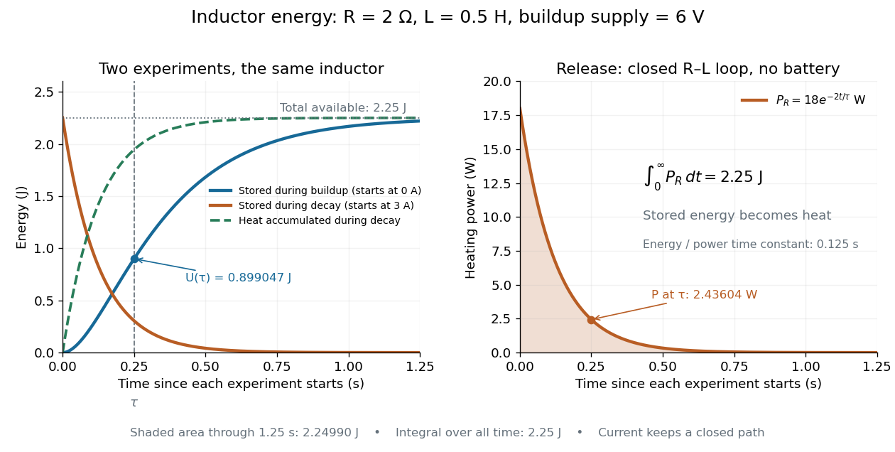
During the closed-loop release in RL circuit, stored magnetic energy plus accumulated Joule heating stays . A real coil also has electrical resistance, so its Joule heating must be included separately from ideal inductor storage. The constant- formulas assume a fixed linear magnetic response.
Following a change in applied electromotive force, a series inductor and resistor obey . For a constant applied electromotive force, the difference from the final electric current decays as . Neglecting self-inductance is justified only when the forcing varies slowly compared with the time constant , or when considering a steady state.
For an ideal linear inductor, . Integrating shows that voltage with no impulse preserves current continuity at switching. This supplies an initial condition independently of capacitor voltage continuity; the two state variables must not be replaced by an assumed zero current derivative.
An ideal voltage source and series resistor feed parallel branches and . Thévenin's theorem gives and . Starting with zero inductor current, and . Switch-on heat in is . Disconnecting the source leaves the stored magnetic energy to dissipate through , with time constant .
For a reversible device with flux linkage , electrical power is , so stored energy changes by . This reduces to only for a fixed linear inductance. Hysteresis makes energy path dependent and introduces loss.
Articles by others on the same topic


Inductance is a property of an electrical circuit that quantifies the ability of a component, typically a coil of wire (known as an inductor), to store energy in a magnetic field when an electric current passes through it. It is defined as the ratio of the induced electromotive force (EMF) in the coil to the rate of change of current flowing through it.