
An RC low-pass filter places a resistor between input and output, with a capacitor from output to their common return. The ideal model prescribes the input electric potential difference and leaves the output unloaded. It is a first-order low-pass filter with unit eventual gain.[ref]
Lab 3: Filters by University of Colorado Boulder, Physics Undergraduate Labs. Lab 3: Filters, §5.4: RC topology and voltage transfer
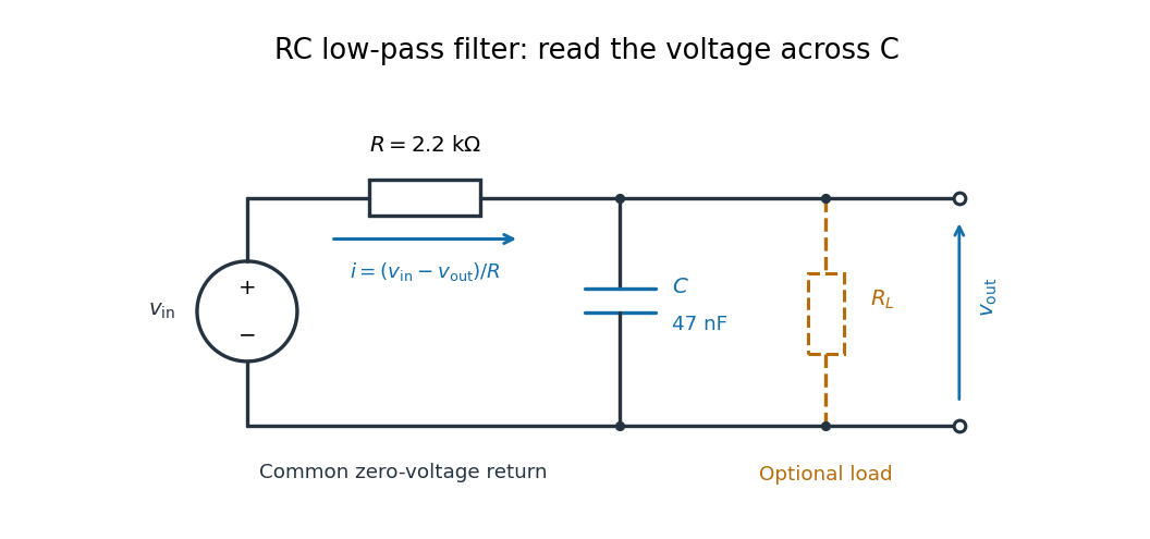

For electrical resistance and capacitance , Ohm's law gives the electric current through the resistor as . The capacitor relation gives . Equating them by Kirchhoff's current law yields the ordinary differential equationThe time constant has units of time. A rapid change in electric potential difference requires a large electric current into the capacitor; the finite electrical resistance limits that rate. A slowly maintained voltage instead lets the capacitor approach the input voltage. The same equation therefore predicts both smoothing of sustained oscillations and a rounded response to a sudden change.
New to topics? Read the docs here!