
A thin lens models an optical lens by collapsing its refracting surfaces into one plane, neglecting thickness relative to the relevant radius of curvature values and object and image distances. Here use an ideal converging thin lens in air and the paraxial approximation: light rays make small angles with the optical axis, so Snell's law can be linearized using the small-angle approximation. Equal surrounding refractive indices on both sides give the familiar symmetric equation.[ref]
Put the thin lens at , with incident light travelling to the right. An object at has . The image coordinate is : for a real image and for a virtual image. The converging thin lens has focal length , and heights are signed relative to the optical axis. The thin lens equation and transverse magnification areThe expression for requires . Negative transverse magnification means inverted; positive transverse magnification means upright. Remember that the positive distance differs in sign from the object's coordinate . [ref]
https://openstax.org/books/university-physics-volume-3/pages/2-4-thin-lenses. Ling, Sanny and Moebs, OpenStax University Physics Volume 3, §2.4: Sign conventions
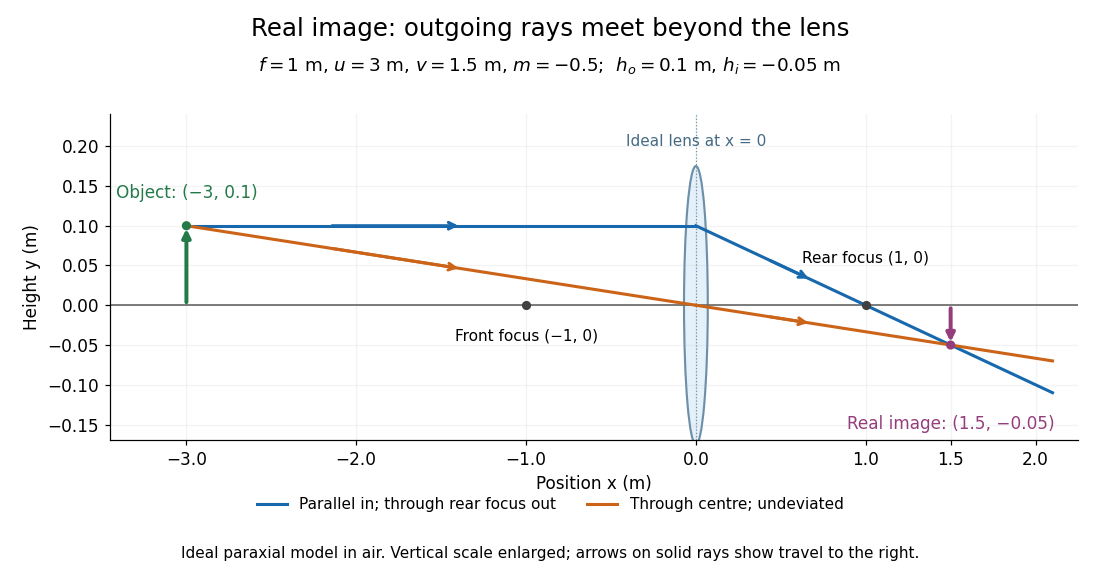
.For focal length , object distance , and object height , calculation givesThe real image is inverted, half as tall, and located to the right of the thin lens. A screen at that position receives the image because the outgoing light rays actually meet there.

For the same focal length and object height , move the object inside the front optical focus, to . ThenThe virtual image is upright, twice as tall, and apparently to the left of the thin lens. Outgoing light rays still travel to the right; only their backward extensions intersect at the virtual image. A screen there cannot collect that image from the outgoing bundle. This geometry explains why a converging optical lens can act as a magnifier when held close to an object. [ref]
https://openstax.org/books/college-physics-2e/pages/25-6-image-formation-by-lenses. Urone and Hinrichs, OpenStax College Physics 2e, §25.6: Virtual images inside the focus
.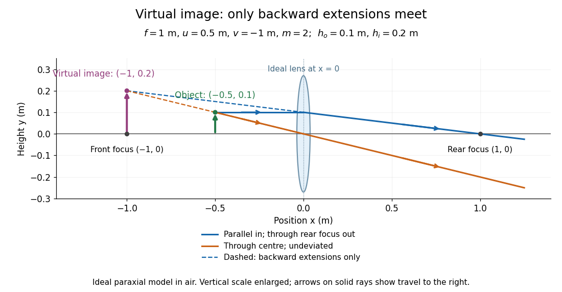

Both diagrams use two rules for ray tracing. A light ray from the object's tip parallel to the optical axis reaches the thin lens at and exits along the straight line through the rear optical focus . Another light ray through the centre continues undeviated in the ideal thin lens model. Their intersection, or the intersection of their backward extensions, locates the image tip. [ref]
https://openstax.org/books/university-physics-volume-3/pages/2-4-thin-lenses. Ling, Sanny and Moebs, OpenStax University Physics Volume 3, §2.4: Ray tracing
.A short geometric proof outline makes the signs transparent. The two outgoing straight lines areFor nonzero , equating their heights at gives , hence the thin lens equation; the centre light ray gives , hence the transverse magnification. This derives the image equations from the ideal ray tracing rules, whose physical justification comes from Snell's law in the paraxial approximation.
At , the two outgoing straight lines are parallel: there is no finite image position. For the real image has ; for the virtual image has . These cases let an optical camera designer choose a receiving position and let a user understand a magnifier. An actual optical lens has finite apertures, which cause diffraction and impose diffraction-limited resolution; optical aberrations can further blur the image. The diagrams are ideal geometrical optics, with exact coordinates within that model, rather than exact predictions of Maxwell's equations. [ref].
New to topics? Read the docs here!