On 11 December 1924, Edward Victor Appleton and Miles Aylmer Fulton Barnett perform an experiment: the Bournemouth broadcasting radio transmitter slowly changes wavelength; an Oxford radio receiver records alternating maxima and minima from ground wave-skywave wave interference. The inferred equivalent height is about . A separate comparison of simultaneous loop and vertical antenna signals tests the downward arrival direction. The E layer is established first; the higher F layer is found in winter 1926–27. These dates describe different findings.[ref]
The Ionosphere by Edward Victor Appleton. Edward V. Appleton, The ionosphere, Nobel lecture, 12 December 1947, printed pp. 80–81, Fig. 1, Eq. (1), and the wavelength-change and antenna-comparison paragraphs
Why change the wavelength deliberately? Ordinary fading alone could arise from changing emission, receiver drift or a moving propagation path. A controlled sweep predicts a specific progression of phase difference between two arrivals. The directional antenna comparison supplies an independent kind of evidence for an overhead contribution. Agreement supports an atmospheric return; fitting a distance alone would not establish a unique electron density profile. In the model below, comparable received amplitudes make the interference fringes easier to see. A practical repetition would also calibrate the frequency sweep, track radio transmitter output and receiver gain, and compare repeated sweeps with fixed-frequency intervals to detect time drift. These are controls inferred from the measurement model, rather than additional procedures attributed to the historical account.
The radio receiver does not need to resolve two pulses to detect two paths. If one path takes longer, the two contributions reaching the receiver during a slow frequency sweep carry slightly different emission frequencies and can produce a slow beat in the detected amplitude. At strictly fixed frequency with stationary paths, the arrivals instead have a fixed phase difference: there is no continuing beat merely because one path is longer. This distinction connects the historical observation to ionospheric interference fringe spacing.
Consider an original two-path model with a locally flat ground baseline and a symmetric equivalent return height . Replace the skywave by two straight segments traveling at the speed of light , and replace the ground wave by a straight segment of length . Their lengths and positive excess distance areThis is an equivalent geometric construction, not a metallic layer overhead. It neglects the curvature of Earth, refraction within the return region, ground-induced wave phase shifts and optical dispersion.
For received complex amplitudes and , absorb their constant relative wave phase into and choose their magnitudes nonnegative. An ideal detector reading proportional to squared received field hasAssume and are independent of frequency across the sweep, with slowly changing amplitudes. Consecutive maxima differ by in phase difference, soThe often-used approximation therefore carries a frequency-independent-path assumption. Counting complete fringe periods between and gives ; equivalently, when the vacuum wavelength is . Count whole periods, not maxima plus minima as though each were a whole period.
Choose and , with . Then , and . A sweep covers four full fringe periods. Conversely, the inferred equivalent height isThese chosen values illustrate the inversion; they are not a transcription of the 1924 measurements. With and , the normalized reading ranges from to : incomplete cancellation does not remove the distance information.
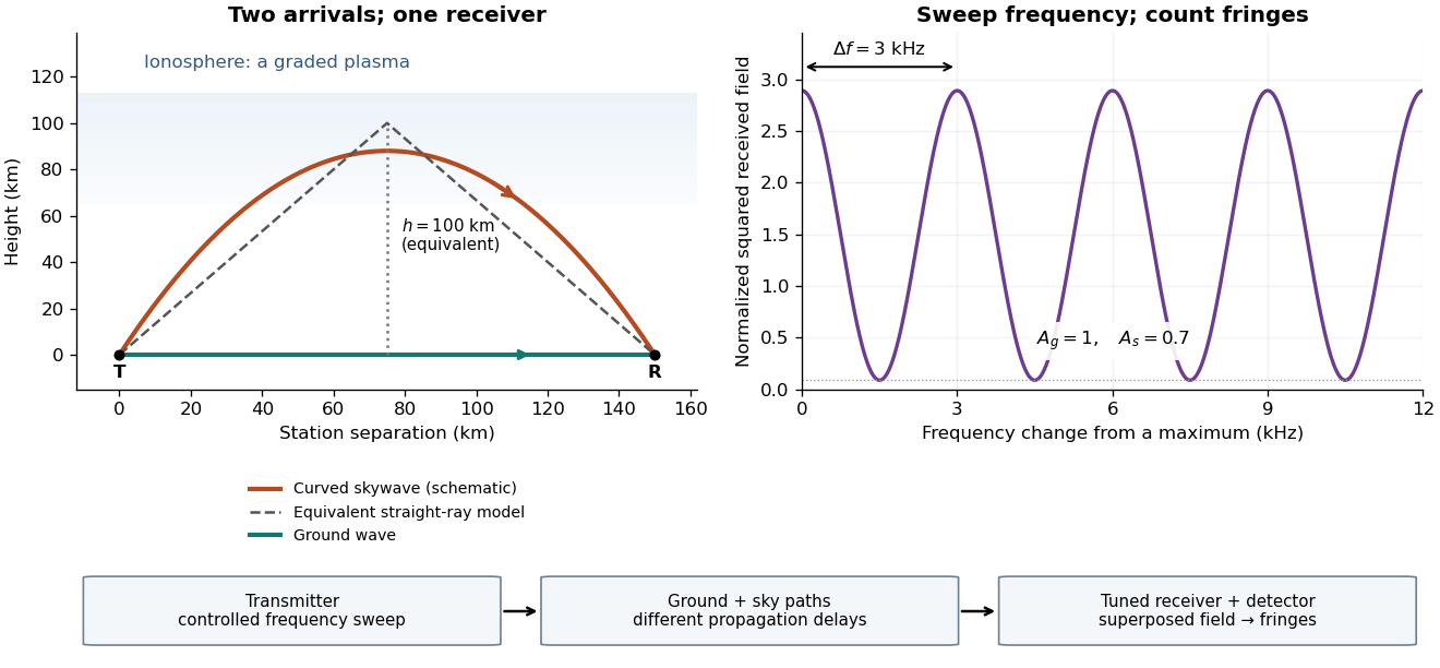

For a sweep with linearly changing frequency and two constant delays , the received instantaneous frequency difference has magnitude . In this model , giving a beat frequency . Equivalently, traversing each of the sweep crosses one fringe. This calculation requires a sufficiently slow sweep that propagation, tuning and amplitude changes can be treated consistently; it is not a beat between two independent transmitters.
More generally, measure the total phase difference , including propagation and any reflection or apparatus contribution. Define the differential group delayFor a locally monotone wave phase with slowly varying derivative, the local spacing is . If , this becomesHere is a phase-equivalent optical path difference, not necessarily the geometric excess distance . A drifting ionosphere, several simultaneous skywaves, changing wave polarization, a frequency-dependent reflection wave phase or significant loss can invalidate the simple constant-spacing inversion.
Articles by others on the same topic
There are currently no matching articles.