Refraction changes the direction of a transmitted wave when it crosses between media with different phase velocities. For light at a planar interface, Snell's law relates the angles measured from the normal vector through the refractive indices. At normal incidence the direction remains unchanged even though the wavelength and phase velocity can change. The worked example under geometrical optics distinguishes transmission from total internal reflection.
For light, refraction explains why a submerged object looks nearer the surface and why an optical lens can form an image. A wavefront crossing a boundary must retain a consistent wave phase along that boundary: its normal spacing changes with phase velocity, and oblique light rays change direction. Normal incidence separates these two effects especially clearly.
Take stationary, transparent, homogeneous media with isotropy, linearity of their optical response, and real positive refractive indices, at one chosen frequency . With the vacuum speed of light and the vacuum wavelength, medium hasThe frequency is unchanged at a stationary boundary; the phase velocity, wavelength and wavenumber can change. Here is a phase refractive index, not the group refractive index. If there is optical dispersion, evaluate at this same frequency on both sides.[ref]
27.1 The Wave Aspect of Light: Interference. §27.1, paragraph preceding equation 27.2 and equation 27.2: unchanged frequency and wavelength in a medium
For an original idealized air–water example, stipulate and , with vacuum wavelength . Then , the water phase velocity is , and its wavelength is . At an air angle of incidence , Snell's law gives a water angle of refraction . These stipulated values illustrate the relations; actual refractive indices depend on material conditions and frequency. By reversibility of an optical ray, the same path emerging from water has outgoing air angle .
The angle of incidence is the angle between the incident light ray and the line of the surface normal vector at the point of incidence. Use the acute angle on the incident side, with for a nongrazing incident light ray. An angle measured from the surface itself is its complement . The same convention applies to wavevectors in the transparent media with isotropy considered here.
The angle of refraction is the angle between the transmitted light ray and the surface normal vector, measured on the transmitted side. With positive refractive indices, a propagating transmitted light ray satisfies in Snell's law. The incident and transmitted angles are measured from the same normal line, not from the surface and not from the emergent light ray at a second surface.
At normal incidence, the incident light ray follows the surface normal vector. Snell's law gives for positive refractive indices, so the transmitted light ray does not bend. Nevertheless, its phase velocity and wavelength change if the refractive index changes. A single axial light ray therefore cannot measure apparent depth: neighboring light rays and their directions supply that information. A reflected component can still be present; no bending of the transmitted light ray does not imply complete transmission.
At a stationary, uniform planar boundary, incident and transmitted plane waves have the same variation of wave phase along the interface and in time. The figure marks places where equal-wave phase wavefronts meet the boundary. Although their perpendicular spacing differs, their intersections must advance along the boundary together. This is the local mechanism behind Snell's law.[ref]
Laws of Geometric Optics. equations 946–950: common angular frequency and matching tangential wavevector components
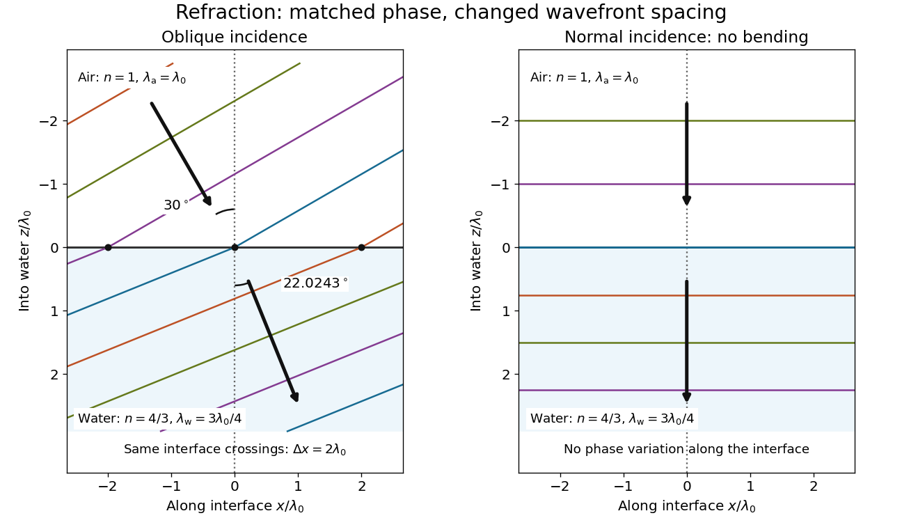
Wavefront spacing changes while interface wave phase matches
. Original plane wave construction for , and air incidence . Both panels have equal horizontal and vertical coordinate scales in units of vacuum wavelength . Coloured lines join at identical interface crossings; arrows show propagation perpendicular to each wavefront. The reflected branch is omitted. At normal incidence, the wavefronts stay parallel to the boundary and only their spacing changes. Details.For a short derivation, let run along the interface and increase into the transmitted medium. Write each wave phase as . The electromagnetic boundary conditions must hold at every on ; their matching requires and . Constant offsets and wave amplitudes are determined separately. Since , this givesFor nonzero tangential wavenumber, the spacing of equal-wave phase intersections along the interface is . It is not the perpendicular wavelength. At normal incidence, the tangential wavenumber vanishes and the interface is uniform in wave phase.[ref]
A submerged object looks shallower because its emerging light rays bend away from the surface normal vector. Their backward extensions give an approximate virtual image nearer the surface. For an object at perpendicular depth in a medium of refractive index , viewed through a flat boundary from a medium of refractive index , the near-normal paraxial approximation gives . Thus the model water depth appears approximately from air. This is a bundle-of-light rays statement, not a deflection of the axial light ray.[ref]
For general transmitted light rays, specify what “depth” means. Put the object at below a horizontal boundary . A light ray reaches the boundary at , with object-side angle and observer-side angle , both measured from the upward normal vector. For , its backward extension meets the object's normal line at , whereThis axis-intercept depth is exact for that one transmitted light ray in the stated model. It tends to as the angles tend to zero; at exactly zero the quotient is interpreted as a limit. These elementary tangent, sine and cosine relations show precisely where the small-angle approximation enters.
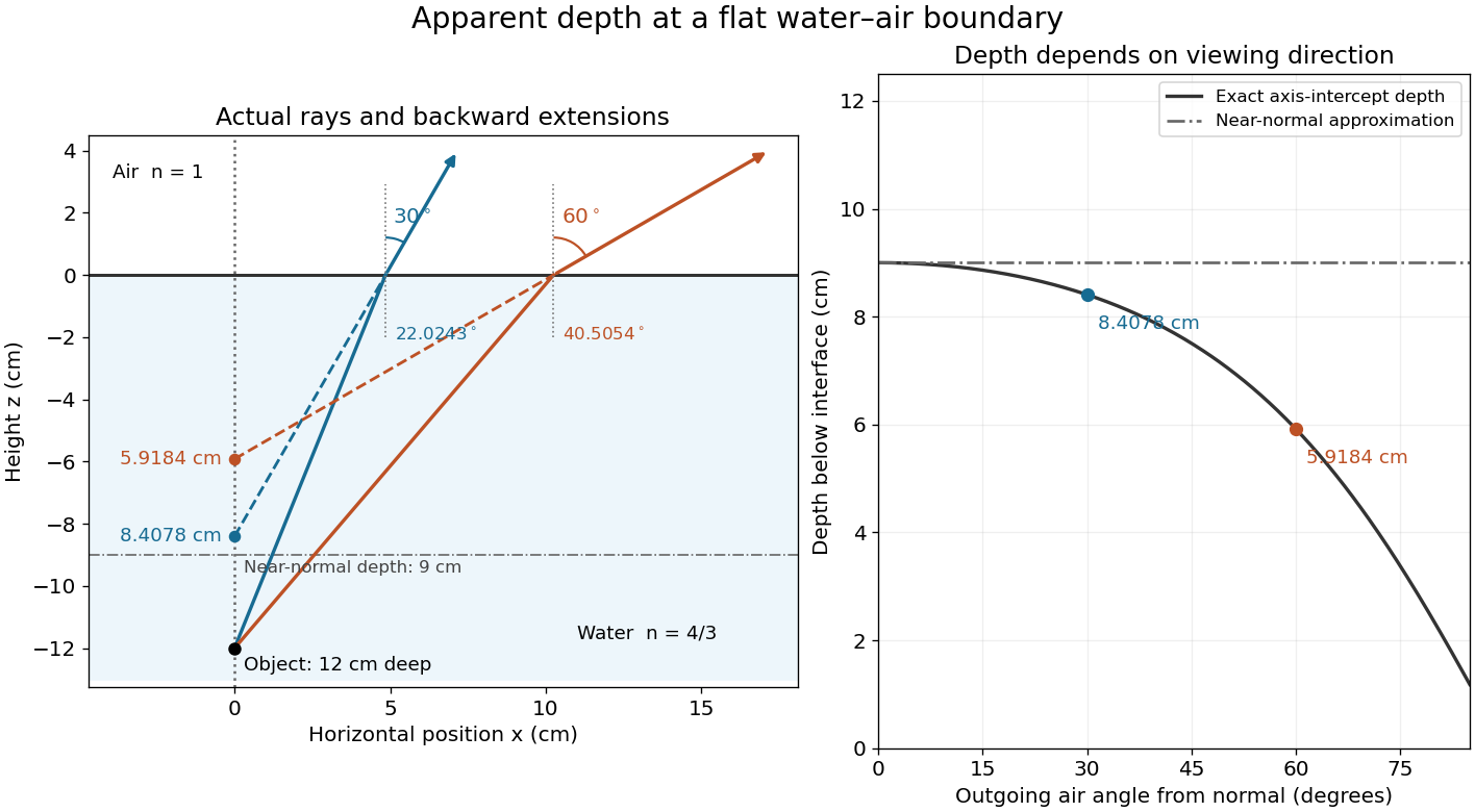
Exact light ray extensions and the near-normal apparent-depth approximation
. Original model of an object below a planar water–air boundary, with refractive indices and . The left panel has equal coordinate scales; solid lines are forward light rays and dashed lines are backward extensions to the object's normal line. The two outgoing light rays are different viewing directions, not a bundle entering one eye. The right panel compares their exact axis-intercept depths with the near-normal value . Marked points are calculated predictions, not observations. Details.At appreciable obliquity these depths differ, so the full outgoing bundle has no single exact virtual image on the object's normal line. An oblique eye samples a narrow bundle; its local apparent position also depends on that bundle and cannot be inferred by declaring to be a universal image depth. A plane refracting boundary gives approximate image formation near normal incidence, with departures at larger angles. The construction assumes a flat surface, uniform transparent media with isotropy, and a propagating transmitted light ray; it does not extend to total internal reflection.
Use a slit light source, a rectangular transparent block on plain paper, pencil, ruler and protractor. Trace the block outline, keep it fixed, and mark widely separated points on incident and emergent light rays. Remove the block and join the entry and exit points to reconstruct its internal light ray. Draw the surface normal vector at entry; measure outside and inside from that normal line. Choose a path exiting the opposite parallel face rather than a side edge. Repeat for a range of with the same block and source colour; record and repeat-reading spread. Plot vertically against horizontally: Snell's law predicts slope , approximately the block's refractive index. The emergent light ray should be parallel to the incident one. Beam width, pencil marks, protractor resolution, block movement and colour spread limit precision; a narrow-colour source reduces spread from optical dispersion. These are measured angular readings, not a direct timing of phase velocity.[ref]
A normal incidence trial checks the drawn normal and the absence of bending, but the ratio is then . Small nonzero angles also make that ratio sensitive to reading errors. Compare several trials through the slope rather than relying on one nearly axial pair. This rectangular-block measurement complements the existing total internal reflection experiment, which probes a different boundary condition.
Articles by others on the same topic

Refraction is the bending of light (or other waves) as it passes from one medium to another with a different density. This phenomenon occurs due to the change in the speed of light as it moves between different substances, such as air, water, or glass. When light enters a denser medium (like from air to water), it slows down and bends toward the normal (an imaginary line perpendicular to the surface at the point of incidence).