Gear mesh stiffness describes the force response of the engaged tooth contacts to a specified relative approach along the mesh direction. In the linear parallel-contact model underlying gear tooth load sharing, all active pairs have the same approach andThe sum assumes compatible displacement coordinates. Adding a bending stiffness, a torsional stiffness and a normal contact stiffness without transforming their coordinates would be dimensionally and mechanically inconsistent.
For an original example, two zero-gap pairs with and give . A load produces normal approach. If only the first pair is engaged, the same ideal stiffness model instead gives .
With gaps or nonlinear response, specify whether the reported value is secant stiffness from a reference or the local gear mesh tangent stiffness . Supposewhere is measured in micrometres and the result in newtons. The second pair starts carrying load at , corresponding to . At , approach is , so the origin-based secant stiffness is about while tangent stiffness is . At the ideal corner itself, a unique two-sided derivative does not exist.
A small-perturbation experiment can hold contact position and mean load approximately fixed, apply a controlled force increment and measure the corresponding relative displacement. Shaft and support mechanical compliance must be separated or included explicitly in the reported system response. Rotating the mesh changes contact position, so one scalar does not necessarily describe a whole cycle.
This matters dynamically: changes in gear mesh stiffness can alter oscillatory response and gear tooth load fractions. The primary NASA analysis used an improved tooth-stiffness model coupled to dynamic-load calculations, rather than prescribing stiffness independently of the load solution.[ref]
Predicted Effect of Dynamic Load on Pitting Fatigue Life for Low-Contact-Ratio Spur Gears by David G. Lewicki. Summary, printed p. 1, modified TELSGE and stiffness–dynamic-load iteration
The elementary parallel-spring sum explains the linear limit, while real contacts require a stated engagement and deformation model.The gear mesh tangent stiffness is the local derivative of total mesh force with respect to a specified relative approach, with contact position and other state variables held fixed:It predicts a sufficiently small incremental force . Unlike a reference-based secant stiffness , it describes the local response rather than the whole loading interval.
For away from any gear tooth engagement threshold,Only members of the gear mesh active-contact set contribute. With , and gaps and , the gear mesh tangent stiffness is before the second contact and after it. At approach , an additional gives more force within the same branch.
The ideal transition at has distinct left and right derivatives. A centered finite difference with any sufficiently small positive giveswhere numerical displacements are expressed in micrometres. The value is the mean of the two branch slopes; it does not establish a unique derivative at the corner, even as shrinks.
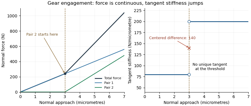
Original unilateral-contact model: continuous force, a gear tooth engagement threshold, and distinct one-sided gear mesh tangent stiffness values
. Details. 
The measured displacement channel also matters. If a contact stiffness is in series with support stiffness , their mechanical compliances add, givingA measurement spanning the whole assembly would therefore not isolate the contact stiffness.
For a perturbation experiment, report the mean load, mesh position, displacement endpoints and whether the increment crosses a contact transition. A primary NASA analysis used a coupled tooth-stiffness/dynamic-load calculation; the derivative above explains a local quasistatic limit, rather than replacing that dynamical model.[ref]
Articles by others on the same topic
There are currently no matching articles.