A gear is a toothed mechanical element that transmits motion and torque through contact with another gear or a rack and pinion. The teeth maintain a prescribed relation between the motions: unlike a smooth friction drive, the ideal gear ratio is set by geometry and tooth counts. The gear pitch circle supplies an imaginary rolling geometry for describing that relation; it is not the circle through the tooth tips.[ref]
For two external gears on fixed parallel axes, let be their tooth counts and let signed angular velocities use the same orientation. Each tooth on one gear must pass a tooth space on the other, so counting tooth passages givesThus a 20-tooth input driving a 40-tooth output makes the output turn half as fast in the opposite direction. An input of revolutions per minute gives an output of revolutions per minute in magnitude. These signs describe an external pair; a rack and pinion instead converts rotation into translation.
The useful trade is between angular speed and torque. In an ideal steady transmission, conservation of energy equates input and output power, . The same 20-tooth/40-tooth pair therefore turns an input torque of into an output torque of while halving angular speed. This does not create energy: more torque accompanies less angular displacement per input revolution. Real gears dissipate energy through friction, and backlash permits a small lost motion on reversal; tooth strength and bearings, rather than the gear ratio alone, determine allowable load.
A face gear is a gear whose working teeth occupy an annular face and mesh with a mating cylindrical pinion. A common arrangement turns the drive through approximately a right angle; other shaft angles and tapered configurations are possible. Its working surface geometry must maintain compatible tooth contact, rather than simply placing ordinary cylindrical teeth on a flat disk.
Tooth counting still supplies an ideal speed relation. If the pinion has teeth and the face gear , equality of tooth-passage rates givesAn original 20-tooth pinion driving a 100-tooth face gear at revolutions per minute therefore gives revolutions per minute at the output. Rotation signs require a stated orientation of the two different shaft axes; the scalar minus sign for an external parallel-axis spur gear pair cannot be copied without that convention.
The annular layout also explains a geometric design issue. With tooth positions, angular spacing is , while arc spacing on a ring of radius isFor , radii and give arc spacings about and . This radial change does not prescribe two interchangeable gear modules; it shows why a generated face-tooth surface cannot be understood as a single extruded cylindrical tooth profile.
A primary 2002 program built a scaled-power split-torque transmission with two opposed face gears, two input pinions and two idlers.[ref]
Development of Face Gear Technology for Industrial and Aerospace Power Transmission by Gregory F. Heath and others. Introduction, printed pp. 1–2, proof-of-concept arrangement; Conclusions, printed p. 84, off-90-degree tapered configuration
Multiple meshes make the geometry useful for distributing and recombining load, but also make alignment and compatibility important.A bench rotation check can test the tooth-count ratio. A gear contact marking test, dimensional inspection and load-sensitive measurements address different questions about the manufactured surfaces and their operation. Correct output speed alone does not establish an acceptable gear contact pattern, tooth stress or gear efficiency.
Gear surface pitting is local loss of tooth-flank material associated with repeated contact loading and mechanical fatigue. The pits alter the surface geometry and can produce debris in the lubricant. This failure mode concerns the loaded flank; it must be distinguished from a tooth breaking through its section. Hertzian contact provides a basic elastic contact-stress model, while actual fatigue depends on the material, lubrication, load history and surface condition.[ref]
Predicted Effect of Dynamic Load on Pitting Fatigue Life for Low-Contact-Ratio Spur Gears by David G. Lewicki. Summary, printed p.1; Summary of Results, printed p.11, dynamic loads and surface-pitting fatigue predictions
A practical inspection can record a gear pitting area fraction , provided the inspected flank region and image scale are fixed. An original example with0.80mm² of projected pit area in a40mm² inspected region gives , or2%. The same fraction in a smaller region need not represent the same damaged volume or depth. Consistent illumination and a stated area convention are needed before comparing successive inspections.
A2009 NASA study provides a motivating experiment. It analyzed24 sets of tapered involute spur pinions meshing with face gears in an endurance program. Vibration measurements were compared with an in-line oil-debris sensor whose coils detected passing metallic particles. Repeated inspections connected the signals to actual tooth-surface damage. The paper found debris responses for the pitting failures, while vibration indicators differed in their ability to detect different damage patterns.[ref]
Gear Fault Detection Effectiveness as Applied to Tooth Surface Pitting Fatigue Damage by David G. Lewicki and others. Printed pp.1–5, test gears, instrumentation, inspection history and indicator comparison
The experiment illustrates why one spectral amplitude is insufficient to identify pitting. The damaged geometry, its position among the teeth and the transmission path all affect a gear vibration spectrum. Combining repeated surface inspection with vibration and debris measurements tests a damage interpretation more directly than labeling every rise at gear mesh frequency as a pitting event.
The gear pitting area fraction measures how much of a stated tooth-flank inspection region is classified as affected by gear surface pitting:Both areas must use the same geometric convention. A projected photograph, an unwrapped flank map and an actual curved surface need not assign the same areas. The gear pitting inspection mask specifies which part of the flank is included, so that an apparent change of damage is not merely a change of inspected region.
For an original image-counting example, let the inspected region contain equal-area pixels and let be classified as pitted. If their common scale is length units per pixel,Thus out of gives , or . The common scale cancels from the ratio; uncertainty in the classification boundary, perspective distortion or the inspection mask does not. Image segmentation should therefore be checked against the actual surface, with consistent illumination and a recorded threshold or classification rule.
Combining regions requires area weighting. Suppose one region has of pits within and another has within . Their fractions are and , but the combined fraction is , rather than the unweighted average .
The ratio measures extent under its chosen convention, not pit depth, lost volume or a universal remaining life. A 2009 NASA endurance study paired repeated gear inspection with vibration and oil-debris monitoring. Its test rig used accelerometers, shaft timing signals and an inductive debris sensor, giving observations of different aspects of the evolving damage.[ref]
Gear Fault Detection Effectiveness as Applied to Tooth Surface Pitting Fatigue Damage by David G. Lewicki and others. Printed pp. 1–5, apparatus, instrumentation, test procedure and inspection comparisons
A surface fraction can complement these measurements, but it does not make their signals interchangeable.A gear pitting inspection mask specifies the tooth-flank region over which damage is counted. It separates eligibility for inspection from the classification of an eligible location as pitted. The denominator of a gear pitting area fraction depends on this mask, so a change in coverage can change the reported fraction even when the surface has not changed.
For a digital image, let indicate inclusion of pixel and let indicate its classification as pitted. With represented surface area per pixel,The arrays and are different indicator functions. Uniform pixel areas cancel, but an oblique view or a curved-surface map can require nonuniform . A shadow, occlusion or unrecorded region should not automatically count as intact material.
An original example begins with 200 pitted pixels among 10000 eligible equal-area pixels, giving . Cropping to a 5000-pixel region that retains 150 pitted pixels gives . The counted damaged area fell while the fraction rose; this comparison alone cannot establish damage growth.
A gear inspection common-region comparison first uses image registration to put inspections into corresponding surface coordinates. On a common grid, the intersection mask is . Comparing the two pitting classifications within that same region holds the denominator convention fixed. Coverage outside the intersection should still be reported: excluding a newly obscured damaged edge can hide relevant change.
Useful inspection records retain the raw image, mask, geometric mapping, image thresholding or other image segmentation rule, and the reason for excluded regions. A primary NASA gear-endurance study combined inspection history with vibration and oil-debris observations, illustrating why damage labels must remain connected to actual inspected surfaces.[ref]
Gear Fault Detection Effectiveness as Applied to Tooth Surface Pitting Fatigue Damage by David G. Lewicki and others. Printed pp. 2–5, test procedure, instrumentation and inspection comparisons
The mask formalism above is an explicit measurement convention, not a claim that every historical inspection used this pixel algorithm.A gear inspection common-region comparison evaluates repeated surface observations on the same registered portion of a tooth flank. It prevents a changed gear pitting inspection mask from being mistaken for a change in damage. The region must be common in surface coordinates, not merely occupy the same pixel positions in two camera images.
After image registration, let and be inspection-mask indicator functions on one reference grid. Their common mask isIf classifies pitting at time and is represented surface area, defineThe identical denominator makes the difference a comparison within the same eligible area. It does not eliminate errors in registration or image segmentation.
An original example has 10000 eligible equal-area pixels at the first inspection and 8000 at the second, with 7000 in common. In the common region, pitted counts rise from 140 to 210: fractions rise from to , a change of one percentage point or relative to the original fraction. Suppose total pitted counts were 200 and 240 across the separate full masks. Their raw difference, 40 pixels, is not the same quantity as the 70-pixel increase within the common region.
A gear inspection coverage audit should also record the excluded areas and why they disappeared or became newly visible. An intersection-only result can miss damage on an edge that the second camera view no longer captures. Keeping the original images makes that loss of coverage visible to a later reviewer.
Common inputs can correlate the two estimated fractions. In general,This is the usual correlated-input uncertainty propagation, not an assumption that neighboring image pixels are independent.[ref]
Evaluation of measurement data — Guide to the expression of uncertainty in measurement by JCGM. Section 5.2, covariance of correlated inputs
A primary NASA endurance study linked repeated physical inspections with vibration and debris observations; the common-region formalism specifies one way to make such repeated surface measurements comparable.[ref]Gear Fault Detection Effectiveness as Applied to Tooth Surface Pitting Fatigue Damage by David G. Lewicki and others. Printed pp. 2–5, test procedure, inspections and damage comparisons
A gear inspection coverage audit records which parts of a tooth surface were eligible for observation, which were excluded and why. It accompanies a gear pitting area fraction or gear inspection common-region comparison so that a numerical damage statistic can be interpreted against the area actually inspected.
A useful record retains the original image, gear pitting inspection mask, surface-coordinate map from image registration, represented pixel areas and exclusion reasons. Shadow, occlusion and an out-of-frame edge are different from a visible region classified as intact. An audit also distinguishes changes in viewing coverage from changes in the image segmentation rule.
An original calculation shows how missing area limits interpretation. Let inspected fraction and observed pitting fraction both refer to the same target surface. If unseen area has unknown pitting fraction , thenso the gear inspection missing-area bound isAt and , the whole-target fraction lies between and without further information. This is a deterministic range over missing data, not a statistical confidence interval. A small observed fraction does not alone establish a small whole-target fraction.
For repeated inspections, record areas visible only initially, only later and at both times. A common-region result can be valid for its intersection while becoming less representative of the full target if a damaged edge is systematically lost. Increasing pixel count inside the retained region does not recover information about the missing region.
The primary NASA gear-endurance study connected inspection history to vibration and oil-debris observations, illustrating the importance of tying a damage interpretation to physical inspection rather than a signal label alone.[ref]
Gear Fault Detection Effectiveness as Applied to Tooth Surface Pitting Fatigue Damage by David G. Lewicki and others. Printed pp. 2–5, test procedure, inspections and monitoring comparisons
The audit and bound above specify an explicit measurement convention; they do not assert that the historical study used this digital-mask procedure.A gear inspection missing-area bound limits the whole-target pitting fraction using the area actually observed and explicit constraints on the unseen area. It formalizes what a gear inspection coverage audit can establish without assuming that excluded regions resemble visible ones.
Let , let be the observed gear pitting area fraction, and let be the unseen fraction affected by pitting. For a consistent surface-area convention,With only known,The interval width is exactly . Improving classification precision within the visible area cannot by itself remove uncertainty from a completely unseen region.
For an original example with and , the possible whole-target fraction ranges from to . The observed therefore does not prove that the whole surface is below an illustrative criterion. That chosen criterion is not a gear safety or acceptance standard.
The worst-case upper bound meets a target only iffor . At and , at least about coverage is required for this particular worst-case guarantee.
Additional justified information can narrow the range. If a separate observation establishes , then . At and , this gives . The tighter bound depends on the new evidence about the unseen region, not on a mathematical preference for a smaller interval.
These deterministic bounds assume the observed classification and represented areas are correct. Image registration, image segmentation and geometric uncertainties can require additional allowances. They are not confidence intervals and do not describe pit depth or remaining fatigue life. The primary NASA endurance study combined inspection with vibration and debris monitoring; these different observations constrain different aspects of damage.[ref]
Gear Fault Detection Effectiveness as Applied to Tooth Surface Pitting Fatigue Damage by David G. Lewicki and others. Printed pp. 2–5, inspection and monitoring comparisons
Gear face width describes the width of the toothed portion. For a cylindrical spur gear or helical gear, it is measured parallel to the rotation axis, rather than along the slanting tooth trace. A projecting hub need not be part of the toothed width. Manufacturer drawings distinguish face width, hub width and total length as separate dimensions.[ref]
KHK Gear Nomenclature. KHK SSG-R catalog dimensional table: face width E, hub width F and total length G
The available width of one gear is not necessarily the gear effective face width of a pair. For two aligned cylindrical gears with equal width and relative axial offset , a simple interval-overlap model givesAn original pair offset by has only of common axial extent. If a hypothetical normal load were uniformly spread across that extent, mean load per axial width would rise from to . This is bookkeeping for an ideal uniform load, not a tooth-strength prediction. Actual gear face load distribution also depends on alignment and deformation.
For helical gears, width also enters gear overlap ratio:With gear normal module and gear helix angle , reducing engaged width from to reduces ideal overlap from to . The overall gear ratio is unchanged. Width therefore affects engagement and loading even when tooth counts and shaft speeds remain the same.[ref]
Elements of Metric Gear Technology by SDP-SI. D815 technical section, §11, Table11-3, printed T-111, axial overlap ratio
Gear face load distribution describes how tooth-contact load is spread across the engaged gear face width. Equal total transmitted force can produce different local loads when shafts tilt, supports deform or tooth traces are imperfect. A geometrically available gear effective face width therefore does not establish uniform loading. The manufacturer's tooth-flank gear face load factor accounts for support arrangement and the expected quality of contact under load.[ref]
Elements of Metric Gear Technology by SDP-SI. D815 technical section, §17.2.12, printed T-164 and Table17-11, tooth-flank load distribution factor
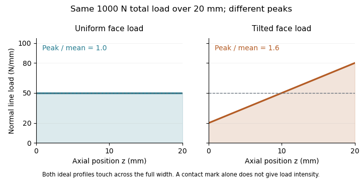
For a simple axial line-load model, let have units over . Its total normal force isUniform loading gives . An illustrative tilted distribution isIts integral remains , while its largest line load is . With , and , the two edges carry20 and80N/mm, compared with the50N/mm mean. The peak-to-mean ratio1.6 characterizes this constructed model; it is not a substitute for the manufacturer's standard factor calculation.
The gear contact pattern can reveal where mating tooth flanks touch, but an unloaded marking test alone does not measure the operating force density. A loaded comparison must specify applied torque, shaft positioning and support deformation. In helical gears, changing tooth-contact lines and multiple simultaneous contacts also require a consistent choice of time and projected width. A wider tooth can reduce mean load per width while still suffering a concentrated edge load; width and alignment must be considered together.
A gear contact pattern is the observed region of tooth-flank contact during a stated mesh test. Its position and extent reveal how the installed tooth surfaces meet. A gear contact marking test uses a thin marking layer and controlled rotation to make that region visible; the mounting position, transmission direction and applied torque belong in the test description. Manufacturer guidance treats surface-contact checks as evidence about the assembled mesh, including shaft alignment.[ref]
A useful bench comparison holds the gear pair and test conditions fixed, records the initial mark, then changes one alignment setting and repeats the test. A mark moving toward one face edge indicates a change in where the flanks meet. This is an observation of contact location, rather than an automatic measurement of operating pressure or a universal diagnosis of the alignment error.
For example, a mark occupying the full20mm gear effective face width is compatible with a hypothetical uniform line load , but also with the tilted positive distributionBoth integrate to1000N, yet their peak line loads are50 and80N/mm. Merely observing full-width contact cannot choose between those gear face load distributions. The gear face load factor or local stress needs additional load/deformation information.
Loaded and lightly loaded patterns can also differ because shaft, housing and tooth deformation change the gap. A quantitative loaded assessment may use strain measurements or a validated contact model alongside the pattern; the2006 gear-rating standard explicitly distinguishes comprehensive load assessment from the limited information in a bearing pattern.[ref]
A gear contact marking test makes a gear contact pattern visible by using a thin contrasting marking layer and rolling the mating gears under stated conditions. The observed transfer or removal of the layer locates the region where the flanks meet closely enough to mark. A useful test record includes the marked flank, rotation direction, mounting position, backlash and applied torque. Manufacturer guidance discusses tooth-surface contact as an assembly and alignment check.[ref]
A controlled comparison changes one alignment setting while keeping the same marking method and loading condition. A shift of the mark toward an edge then records a change in the mesh geometry. Changing layer thickness at the same time would confound that comparison: the visible pattern is the response of the surfaces and the marking process together.
An original threshold model illustrates this limitation without claiming a universal paint law. Suppose an unloaded gap over a face isStipulate that a mark appears wherever , with gear marking-layer gap threshold . At the marked width is ; at it is . The indicated coverage doubles even though the underlying gap is unchanged. Real transfer also depends on deformation and the marking material.
Nor does a broad mark uniquely determine the gear face load distribution. Operating torque deforms teeth, shafts and supports, so a lightly loaded pattern can differ from a loaded one. The historical gear-rating standard distinguishes comprehensive loaded assessment from the limited information in a bearing pattern.[ref]
A meaningful validation pairs the pattern with an independent load-sensitive observation, such as tooth-root strain, or a checked deformation model. The question is whether the setup places contact where intended under the specified condition, rather than whether one visually attractive mark proves uniform pressure at every operating load.
A gear marking-layer gap threshold is an effective separation below which a stated marking process produces a visible transfer or removal of material. It is a model of the observation in a gear contact marking test, rather than a universal thickness or a material constant. Layer thickness, pressure, rolling history and the marking material can all matter; a visible gear contact pattern does not directly give local operating pressure.
For an original idealization, let the unloaded separation across a face beand stipulate a visible mark where . Here is the effective threshold, the minimum gap and its slope magnitude. For a centered pattern on face width , the predicted marked width isChoose , and . Thresholds and give marked widths and . The geometry has not changed; the observation threshold has.
Away from the onset and saturation corners,Here a threshold change changes the indicated width by . In the shallow-gap limit, small changes of the marking process can therefore cause conspicuous changes in the visible pattern.
A controlled comparison should hold the coating method, applied torque and number/direction of roll-throughs fixed, then vary one geometric setting. A separate fixture with known separations can test whether a proposed threshold model describes the marking process, without treating nominal coating thickness as an exact gap measurement.
Manufacturer contact guidance describes patterns as evidence about assembled tooth surfaces, and the historical rating standard limits the load information inferred from a bearing pattern.[ref]
Elements of Metric Gear Technology by SDP-SI. Section 19.1, surface contact of spur and helical meshes, printed T-221
[ref] The threshold equation is a deliberately specified illustrative model; actual deformation and transfer behavior need validation before converting a mark into a quantitative gap or gear face load distribution.A gear face load factor quantifies the effect of nonuniform load across the engaged gear face width. For the contact-load convention in ISO 6336-1:2006, compares maximum line-load intensity with the mean intensity over the stated width:Here is the total load represented by that distribution and is its evaluation width. A uniform distribution gives1; an edge-concentrated distribution gives a larger value. The numerator and denominator must refer to the same load convention and operating condition.[ref]
For an original illustrative distribution over ,total load is1000N, mean line load is50N/mm and maximum line load is80N/mm. Thus . A uniform distribution with the same width and total load gives1. The gear contact pattern can cover the whole width in both cases.
For ideal elastic line contact at fixed geometry and material, Hertzian contact pressure scales with the square root of line load. The corresponding gear contact-stress load factor is therefore in this simplified comparison. Multiplying the contact pressure itself by1.6 would confuse a load-intensity ratio with a stress ratio. This scaling does not replace a complete gear-rating calculation.
The manufacturer's treatment connects face-load assessment to shaft-support placement, shaft stiffness and loaded contact quality.[ref] A value inferred from a toy line-load profile is consequently useful for understanding the factor, while a real design must obtain the relevant distribution or factor from a method appropriate to its geometry and load state.
The gear contact-stress load factor is the multiplier associated with the face-load term in a contact-stress calculation where Hertzian contact pressure scales with the square root of local line load. It distinguishes a stress ratio from the underlying gear face load factor. The historical definition of compares maximum line-load intensity with the mean over the evaluation width.[ref]
For ideal elastic line contact, hold the effective geometry and material fixed. Write the peak pressure aswhere is load per contact length, the effective elastic modulus and the effective radius. If the largest line load is , division by the pressure calculated from the mean line load givesThe square root follows from the pressure model; it is not a second independent multiplier on the load.
For an original example, a face-load ratio gives a stress multiplier . A mean-line-load reference pressure would become under these assumptions. Multiplying pressure directly by would instead give and count the load ratio as though it were a stress ratio. Increasing effective line load fourfold doubles this model pressure.
Small relative uncertainties also scale differently:Thus a small relative change in produces about a relative change in its square root to first order. This sensitivity concerns that term alone; uncertainties in material, geometry and the reference load remain.
A local stress scaling does not predict gear surface pitting life on its own. Contact position, curvature, load history and material response matter. A primary NASA analysis explicitly combined varying tooth loads and contact geometry with a fatigue-life model.[ref]
Predicted Effect of Dynamic Load on Pitting Fatigue Life for Low-Contact-Ratio Spur Gears by David G. Lewicki. Summary, printed p. 1; Analysis, tooth-contact intervals and varying curvature/load
A real rating must keep all factors and load conventions consistent with the chosen method.Gear effective face width is the usable axial width participating in a stated cylindrical gear mesh. It must be distinguished from each component's nominal gear face width, and from a claim that every part of that width carries equal load. The normal/transverse tooth geometry and gear overlap ratio use this engaged width, while gear face load distribution describes how the load actually occupies it.[ref]
Elements of Metric Gear Technology by SDP-SI. D815 technical section, §11, Table11-3, axial overlap ratio; §17.2.12, tooth-flank load distribution
An elementary geometric model treats the two toothed widths as intervals and on their common axial coordinate. Their available overlap isFor one20mm-wide gear occupying and a16mm-wide mate centered at , the second interval is . Their overlap is only12mm. The mean line load for a hypothetical uniformly shared normal force of1200N is then100N/mm, rather than the60N/mm obtained by using the first gear's entire nominal width.
With gear normal module and gear helix angle , gear axial pitch is . The12mm overlap gives geometric gear overlap ratio , compared with for20mm. Axial positioning can therefore alter overlap without changing the ideal gear ratio.
The interval calculation assumes the flanks remain usable throughout their common extent. Relief, damaged regions or partial contact can require a more specific working-width convention. Uneven loading is not generally corrected by shrinking width until a uniform-load formula looks plausible; a stated load-distribution model is needed to predict local loading.
Gear mesh frequency is the rate at which successive teeth pass through a mesh. For a fixed-axis gear with teeth rotating at revolutions per second,where is speed in revolutions per minute and is angular velocity in radians per second. The formula follows by counting tooth passages per complete turn. Both gears of one steady compatible mesh give the same result because their tooth-passage rates agree.[ref]
For an original example, a24-tooth input rotating at1500 revolutions per minute gives . Its60-tooth mate turns at600 revolutions per minute, also giving . The shaft rotation frequencies differ even though the mesh frequency agrees.
A compound gear train can have different mesh frequencies at successive stages. If that60-tooth gear is rigidly joined to a20-tooth gear driving an80-tooth output, the second mesh frequency is . The final output turns at150 revolutions per minute. By contrast, every mesh of an ideal fixed-axis simple gear train shares the same tooth-passage frequency: its intermediate gear engages both neighbors with the same tooth count and rotation rate.
A gear vibration spectrum may contain components at the mesh frequency and its integer multiples, together with other mechanical excitations. Measuring rotation with a rotary encoder lets a test compare observed frequency components with tooth-passage predictions. A spectral peak near does not by itself establish a structural natural frequency or identify a particular defect; the forcing and the system's frequency response both shape measured vibration.[ref]
Structural Testing Part I: Mechanical Mobility Measurements by Ole Døssing. “Trouble-shooting”, printed pp.6–7: response peaks can arise from excitation rather than structural resonance
For trains with moving gear axes, the simple fixed-axis formula requires the appropriate relative rotational rate rather than an unqualified absolute shaft speed.A gear vibration spectrum describes how a measured gearbox motion signal is distributed over frequency. An accelerometer on a housing supplies a response spectrum; a rotary encoder supplies a rotation reference. Gear mesh frequency predicts tooth-passage components, but their observed amplitudes also depend on applied loads, sensor direction and the mechanical frequency response. A response peak alone therefore does not identify a structural natural frequency.[ref]
Structural Testing Part I: Mechanical Mobility Measurements by Ole Døssing. Printed pp.5–7, distinction between signal and system analysis; p.14, response spectrum as force spectrum times frequency response
For an original example, a24-tooth gear at1500 revolutions per minute rotates at and has mesh frequency . Consider an illustrative acceleration signal with amplitude modulation:The product-to-sum identity gives a600Hz component of amplitude and modulation sidebands at575 and625Hz, each of amplitude . For and , each sideband has peak amplitude . Gear vibration order expresses these frequencies relative to the chosen shaft: the central order is24 and the neighboring orders23 and25. These positions follow from the constructed signal, without requiring a damaged tooth.
A primary apparatus example makes that ambiguity concrete. NASA's2015 transmission experiment compared rotating accelerometers on a pinion shaft with stationary housing sensors. The rotating radial channel showed sidebands at1854 and2060Hz around a1957Hz mesh frequency, spaced by the103Hz shaft rate. The report derives this shift from the rotating measurement direction and discusses sums and differences of tangential channels. A measurement-frame effect can therefore create sidebands as well as a mechanical defect.[ref]
A useful test records speed, load, mounting and sensor orientation with each spectrum. If speed changes appreciably within one record, fixed-frequency lines can spread; comparisons should then account for the changing rotation rate. Record duration also controls Fourier frequency resolution. Sideband changes are evidence to interpret alongside a baseline and the test conditions, rather than a unique diagnosis from one spectral peak.
Gear vibration order expresses the frequency of a measured vibration component relative to a specified shaft's rotation rate:Here is frequency in hertz and is shaft speed in revolutions per minute. The dimensionless order is cycles per shaft revolution. It must name the reference shaft: the same gear mesh frequency has different orders relative to the two gears in one mesh. Order tracking follows such rotation-related components as speed changes.[ref]
ordertrack: Track and extract order magnitudes from vibration signal by MathWorks. Description and orderlist input: extraction of requested orders using a supplied shaft RPM history
For a24-tooth input at1500 revolutions per minute, and mesh frequency is600Hz, so mesh order is24. Its60-tooth mate turns at10Hz, giving mesh order60 relative to that shaft. If the input rises to1800 revolutions per minute, mesh frequency becomes720Hz but input-relative mesh order remains24. An unrelated structural natural frequency at600Hz would instead move from order24 to order20 as reference speed increases.
Angular resampling makes the distinction explicit. Let be shaft angle. A tooth-periodic illustrative signal can spread across many fixed-frequency bins during acceleration, while as a function of angle it remains , with order . Enough angle samples are needed to resolve the desired tooth-related oscillations. This derivation describes the resampling approach; not every order tracking algorithm uses that implementation.
Rotation-synchronous amplitude modulation can produce neighboring modulation sidebands: a24th-order component modulated once per input revolution has orders23 and25. Modulation associated with another shaft need not give integer spacing in the chosen reference. Orders identify kinematic relationships, while amplitudes still depend on loads, mounting and frequency response. A high mesh order or a sideband is therefore not itself a diagnosis of damaged teeth.[ref]
Evaluation of MEMS-Based Wireless Accelerometer Sensors in Detecting Gear Tooth Faults in Helicopter Transmissions by David G. Lewicki and others. Printed p.21, rotating measurement direction produces shaft-spaced sidebands; pp.24–25, rotation-synchronous processing from a reconstructed timing signal
Gear contact ratio measures how much successive tooth engagements overlap. For an external spur gear pair, its transverse value iswhere is usable gear path of contact length along the gear line of action and is gear base pitch. One tooth pair remains engaged while contact advances through length ; successive pairs begin after an advance of . Thus is also the ideal mean number of tooth pairs simultaneously engaged.[ref]
For a tip-limited, noninterfering external involute pair with tip radii , base radii , axis separation and operating pressure angle , right-triangle geometry givesFor an original example, use module , tooth counts 20 and 40, reference angle and standard separation . With tip radii and , the formula gives and , hence .
In the ideal periodic timing model, two tooth pairs are engaged for about of a tooth-passage period and one pair for about . This does not mean that force is divided equally between engaged pairs: tooth flexibility and contact geometry affect load sharing. A value below one would leave gaps in ideal engagement, while a value exactly one leaves no overlap margin for tolerances and deformation.
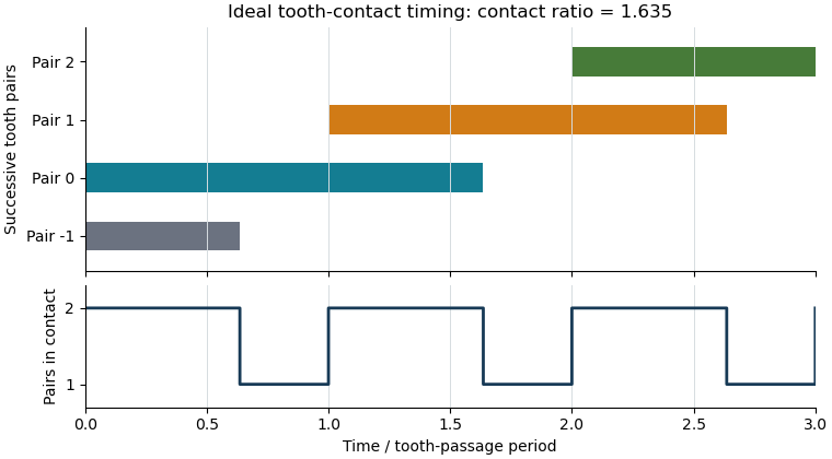
The plot shows contact timing, rather than physical tooth shapes or force sharing. For helical gears, the transverse measure must additionally be distinguished from gear overlap ratio caused by the inclination of teeth across the gear face. Finally, real usable contact can be shortened by modified or unavailable flank portions; the tip-circle formula is conditional on its stated geometric assumptions.
Gear overlap ratio measures the additional engagement overlap caused by a helical gear's tooth inclination across its gear face width. It is distinct from the transverse gear contact ratio, which measures contact length within one transverse section. For face width , reference gear helix angle and gear normal module ,where is gear transverse module and is gear axial pitch.[ref]
Elements of Metric Gear Technology by SDP-SI. §11, Table11-3, “Axial (Overlap) Contact Ratio”, helical-gear equation
Unwrapping the reference cylinder explains the ratio: moving across axial width shifts the tooth pattern circumferentially by . Dividing this shift by gear transverse pitch counts how many tooth spacings the engagement progresses across the face.
For an original example, , and giveDoubling the face width doubles this geometric overlap if the other parameters stay fixed. At the spur gear limit , the overlap contribution tends to zero.
In the ideal cylindrical-helical model, total geometric contact ratio is the sum of transverse and axial contributions, . This does not specify a uniform division of load: flexibility, alignment and the usable flank region affect actual contact. Increasing helix angle can improve overlap while also increasing gear axial force; increasing width also changes the alignment and support demands. These are related geometric tradeoffs, not a guarantee of a specified noise level or load capacity.
A helical gear is a cylindrical gear whose teeth follow a helix around the reference cylinder. The gear helix angle measures their inclination to the axis. In a conventional external pair on parallel axes, mating gears have opposite hands with matching helix-angle magnitudes. Inclination makes engagement progress across the face rather than beginning everywhere along a straight tooth at once, but also creates a gear axial force that the supports must carry.[ref]
A helical gear must specify its reference plane. The gear normal module is based on a section normal to the tooth direction, whereas gear transverse module is based on the plane perpendicular to the gear axis. Their geometric relation isSimilarly, reference pressure angles satisfy . Equal numbers labeled “module” in different planes therefore need not specify interchangeable gears.[ref]
For an original example, take , and . Reference diameter is , rather than . With , the transverse angle is about .
At standard mounting, a transmitted torque gives gear tangential force . Ideal contact-force resolution gives axial magnitudeIts direction depends on helix hand and transmitted-torque direction. The corresponding radial component uses the transverse gear pressure angle. This illustrates the design trade: distributed engagement can improve smoothness, but the same transmission requires axial-load support. The example concerns parallel-axis cylindrical gearing; it should not be applied unchanged to crossed-axis arrangements.
Gear axial force is the component of tooth-contact load parallel to a gear's rotation axis. In a standard parallel-axis external helical gear pair, ideal force resolution at the reference mounting giveswhere is gear tangential force and is reference gear helix angle. Its direction depends jointly on helix hand and the transmitted-torque direction. Reversing the torque can reverse axial thrust even though the cut helix remains unchanged.[ref]
For an original example, transmit through reference radius at standard mounting. Then . A30degree helix gives axial load ; a15degree helix at the same tangential load gives about . The support must sustain the appropriate axial reaction in addition to the mesh's radial and tangential loads.
The axial load does not itself imply energy loss. If an ideal gear has no axial velocity, that force does no work through an axial displacement. Real support friction and deflection can nevertheless affect efficiency and tooth alignment. A useful bench check applies a controlled transmitted torque and measures the axial reaction while recording helix hand and the actual power-flow direction; an unsigned force magnitude alone does not establish the direction rule.
For the ideal spur gear limit, and this geometric thrust term vanishes. Opposite-handed helical sections can be arranged to cancel net axial thrust under suitable symmetric loading, but unequal loading prevents assuming exact cancellation. Away from the stated reference mounting, force formulas must use a geometrically consistent operating convention rather than mixing operating pitch radii with an unrelated reference angle.
Gear transverse module specifies tooth spacing in the plane perpendicular to a cylindrical gear's axis. If is tooth count and is reference diameter, , so reference-circle gear transverse pitch is . For a helical gear, this transverse section differs from the section normal to the tooth direction.[ref]
Unwrapping the reference cylinder makes the tooth direction a slanted line. Projecting its normal spacing into the circumferential direction giveswhere is gear normal module and is reference gear helix angle. At zero helix angle the normal and transverse modules coincide, recovering the spur gear case.
For an original example, take , and . Then and . A compatible 48-tooth gear has reference diameter , giving standard separation . Treating2.5 as the transverse module instead would incorrectly give diameters60 and120mm and separation90mm.
The transverse specification is convenient for reference diameters and axis separations, while the normal specification is convenient for the tooth-normal geometry. A drawing must identify which module and pressure-angle planes it uses; a numerical module value alone is incomplete for a helical gear. These are reference dimensions: a changed operating separation must additionally be interpreted through the mounted geometry, rather than redefining the gear's original module.
Gear normal module is the gear normal pitch divided by , measured normal to the tooth direction of a helical gear. It describes a different section from gear transverse module , which uses the circumferential spacing in a plane perpendicular to the rotation axis.[ref]
If is reference gear helix angle, geometric projection givesFor an original inference example, reference diameter , tooth count and imply but . The normal pitch is approximately , compared with transverse pitch . This is a geometric example, not a claim that the inferred normal module belongs to a particular manufacturer's preferred series.
Conversely, specifying for the same30 teeth and30degree helix angle gives reference diameter . Thus two drawings both labeled “module2” can describe different gears when one means normal module and the other transverse module.
Pressure angles need the same care: for reference tooth geometry, . Matching only a module number, without its plane, pressure-angle convention and helix geometry, does not establish a compatible pair. In a conventional parallel-axis external mesh, the two helical gears also require appropriate opposite hands; the normal-module definition alone does not specify that connection.
Gear normal pitch is the repeat spacing of corresponding helical gear tooth flanks normal to their tooth direction on the developed reference cylinder. It equals times gear normal module . It is a different geometric spacing from gear transverse pitch , measured circumferentially, and from gear axial pitch , measured parallel to the rotation axis.[ref]
Unwrap the reference cylinder into a plane. The equally spaced tooth traces become parallel straight lines making gear helix angle with the axis. Projecting the transverse spacing onto the normal to those traces givesFor reference diameter , teeth and , , whereas . Multiplying by gives about , not the circumference: normal pitch is not the circumferential step.
At , normal and transverse pitches agree, as expected for a spur gear. For nonzero gear helix angle, using one in place of the other introduces a factor . Normal pitch is also distinct from gear base pitch, which refers to the base-circle geometry of an involute. Matching a pitch value without its measurement convention, pressure angle and tooth geometry is insufficient to establish a compatible mesh.
The gear helix angle measures a cylindrical gear tooth's inclination to the rotation axis, normally on the reference cylinder. A straight spur gear has ; a helical gear has a nonzero inclination and a specified hand. The cylinder and reference direction matter because another measurement plane or cylinder radius can give another angle.[ref]
Let be the positive gear lead, the axial advance of one tooth helix in a complete turn, and let the reference diameter be . Unwrapping that cylinder produces a right triangle with circumferential side and axial side :For and , . Doubling the lead on that same cylinder gives angle approximately , rather than15degrees: the relation involves a tangent, not a linear angle scaling.
With equally spaced teeth, gear axial pitch is , where is gear transverse pitch. For nonzero , this also gives . The corresponding axial-pitch quantity diverges in the straight-tooth limit; it is not a finite replacement for the transverse tooth spacing of a spur gear.
Larger helix angle changes reference diameter at fixed gear normal module and tooth count, increases axial thrust for a fixed tangential load, and increases face-overlap geometry at fixed face width. These consequences must be evaluated together with gear contact ratio and support loads. A magnitude such as30degrees does not by itself specify right versus left hand, nor the thrust direction under a particular applied torque.
Gear axial pitch is the axial repeat distance between corresponding flanks of successive teeth of a cylindrical helical gear. The measurement follows a line parallel to the rotation axis on a concentric cylinder. It is not the axial advance of one tooth helix through an entire revolution; that larger distance is gear lead . For equally spaced teeth, .[ref]
On the developed cylinder, neighboring tooth traces separated transversely by gear transverse pitch intersect a fixed circumferential coordinate at axial positions separated by . Their slope givesFor , and gear helix angle , and . The corresponding gear normal pitch is only . These two distances differ by a factor of two in this example because .
For an engaged gear face width , the ideal gear overlap ratio is : successive tooth-contact traces span about1.84 axial pitches across the face. Holding fixed while letting tend to zero makes diverge. Straight spur gear tooth traces do not cross an axial generator successively, so a finite axial-pitch interpretation does not survive that limit. Helix hand determines orientation; the positive pitch magnitude alone does not specify hand.
Gear lead is the axial advance of one tooth helix over a complete turn around a cylindrical helical gear. It differs from gear axial pitch , which steps between successive teeth at one circumferential position. With equally spaced tooth helices, . The lead magnitude does not specify whether the helix is right-handed or left-handed.[ref]
Unwrapping a reference cylinder of diameter gives a right triangle with axial side and circumferential side . Since gear helix angle is measured from the axis,For and , . If , then gear axial pitch is ; confusing the two distances would introduce a factor30.
A useful geometric check keeps the lead fixed while changing the chosen concentric cylinder. The helix's axial advance per revolution remains , but its angle satisfies . For the same lead on diameter , the angle is approximately , rather than . Thus a helix-angle specification needs its cylinder, normally the reference cylinder. Lead can remain finite when the physical tooth is much shorter than one complete turn: it describes the continued helix, not a requirement that the manufactured tooth cover a full revolution.
The gear pressure angle specifies the direction of tooth-normal contact relative to tangential motion. For an external spur gear pair with involute tooth flanks, its operating value is the angle between the gear line of action and the common tangent to the operating pitch circles. The gear line of action is the common normal to the contacting flanks and a common tangent to their gear base circles. Reference gear pressure angle and operating pressure angle coincide at the corresponding reference mounting, but need not coincide at another axis separation.[ref]
Elements of Metric Gear Technology by SDP-SI. §3.1, definition of pressure angle relative to line of action and line of centers
Neglecting friction, let the tooth-normal force magnitude be . Its components areThe gear tangential force transmits torque, , at operating radius . The gear separating force pushes the gear centers apart in the external mesh and loads their supports. Increasing gear pressure angle increases this separating load for the same transmitted tangential load.
For an original example, a spur gear transmits at . Then . At ,If the angle were at the same , the separating load would rise to approximately . This comparison concerns load direction, not gear efficiency: an ideal normal force can transmit power without dissipating it. Actual frictional contact adds another force component and can alter both losses and support loads.
Gear separating force is the component of an external gear mesh load along the line joining the gear centers, tending to push those centers apart. For a frictionless external spur gear pair,where is tooth-normal force, is gear tangential force and is operating pressure angle. This component acts on the shaft supports even when the mesh is ideal and lossless.[ref]
For example, take operating radius and transmitted torque . Then . At , ; at and the same tangential load, . The larger separating load is a change in load direction, not by itself an efficiency loss.
If the gear centers are ideally fixed, this radial component produces no work through a center-separation displacement, since that displacement is zero. Flexible supports can nevertheless deflect under it and store elastic potential energy. The resulting change in axis separation can change operating pressure angle, backlash and tooth contact, so the assumed geometry and support stiffness interact.
A support-load experiment can apply a known torque slowly to a mounted external pair and measure the reaction along the line of centers while maintaining the stated axis separation. Agreement with tests the force resolution under low-friction assumptions. Additional reactions, tooth friction and mounting preload must be accounted for before identifying a measured support force with this mesh component. Internal meshes and nonparallel-axis gearing require their own direction conventions; the external separating-force picture must not be transferred unchanged.
Gear tangential force is the pitch-circle-equivalent force that transmits torque in a gear mesh. At operating pitch radius ,For an external spur gear pair without tooth friction, it is the component of tooth-normal force along the common tangent to the operating pitch circles: . Together with the gear separating force, this resolves the mesh load in fixed shaft-loading directions. It is not a claim that the moving contact point always has that same local radial/tangential frame.[ref]
The relation follows geometrically from the gear line of action. Its distance from a gear center is the gear base circle radius , so the moment of a normal force is . Since , substitution yields .
For an original example, a 20-tooth input with operating radius transmits . Its gear tangential force is . Driving a 60-tooth output at operating radius ideally gives : the pitch-circle-equivalent tangential load is the same, while its moment arm is three times larger. At input angular speed , pitch speed is and transmitted power is , agreeing with .
The calculation assumes steady ideal force transmission. Gear efficiency affects the input/output power balance, while inertia can contribute additional torque during acceleration. A gear tangential force is also not the entire contact load: at , corresponds to normal load about and separating load about .
The gear line of action is the common normal along which ideal tooth contact transmits force. For meshing involute profiles in a transverse plane, it is a straight common tangent to the two gear base circles. The angle it makes with the common tangent to the operating pitch circles is the operating pressure angle.[ref]
Its intersection with the line of gear centers is the gear pitch point. The actual contact point moves along only a finite portion, the gear path of contact, bounded by usable tooth profiles. Thus a diagram's infinite straight line is a geometric construction, not a claim that teeth can contact everywhere on it.
The geometry explains constant ratio. Let the tooth-normal force magnitude be and the base radii . The perpendicular distance from each gear center to the gear line of action is its base radius, so the ideal transmitted moments have magnitudesThese moment arms do not change as the contact point advances along that line. The no-penetration contact condition correspondingly gives for an external pair. Compatible profiles have , recovering the tooth-count gear ratio.
For example, reference radii and at reference gear pressure angle give base radii approximately and . A normal force produces moment magnitudes and . Their ratio stays two as the point of contact moves.
Ideal normal transmission does not eliminate gear tooth sliding. Relative surface slip generally changes along the gear path of contact and vanishes at the gear pitch point for the ideal external pair. Actual friction associated with that slip adds a tangential contact force; its resultant need not lie exactly on the geometric gear line of action.
Gear tooth sliding is relative tangential motion of mating tooth surfaces at their contact point. Ideal contact prevents relative normal penetration but does not generally require the tangential surface velocities to agree. For a fixed-axis external involute pair, tangential slip vanishes at the gear pitch point and changes as the contact moves along the gear path of contact.[ref]
Let be the pitch point, let be a unit vector along the gear line of action, and write a contact location as . With a common positive axis and signed angular velocities , rigid-body velocity differences giveThe velocities at cancel, leaving this term proportional to distance along the contact line. Since has opposite sign in an external pair, the sliding-speed magnitude is .
For an original example, use and . At , gear sliding velocity along the common tooth tangent is ; at it has the opposite sign. At it is zero. Equality of operating pitch-circle speeds must therefore not be used to conclude that the tooth flanks roll without slipping throughout engagement.
In a simplified Coulomb friction model with coefficient of friction and normal load , the dissipated gear sliding-friction loss is . Hypothetical values , and give . This is a local illustrative loss model, not a lubricant specification. Zero ideal sliding at the pitch point also does not eliminate every source of gearbox loss, such as support friction or deformation-related dissipation. Real load and friction can vary through the engagement, so total loss requires integrating the applicable contact model.
Gear sliding-friction loss is the rate at which relative tooth-flank sliding dissipates mechanical energy. In a simple Coulomb friction model with normal contact load , coefficient of friction and gear sliding velocity , the nonnegative dissipated power isThis is a local contact model, rather than the entire gearbox loss. Manufacturer guidance distinguishes gear-meshing losses from losses in rotating supports and warns that overall gear efficiency depends on load and speed.[ref]
Technical Data Gearhead by Citizen Micro. “Gear Efficiency”, meshing/support losses and load- and speed-dependent efficiency
To derive the sign, let along the common tangent. The friction force on surface1 is and that on surface2 is . Their combined mechanical power is . The corresponding positive quantity is the rate of mechanical energy loss. At zero sliding the ideal Coulomb sliding-loss term vanishes, even though another resistance mechanism can remain.
For a fixed-axis external spur gear pair with , gives . Hypothetical and give . Holding these load and friction assumptions fixed while doubling both shaft speeds doubles the instantaneous loss at that geometric point.
Gear friction work per engagement integrates this varying loss through the active gear path of contact. If one pair carries a constant , the contact coordinate runs from to at constant speed , givingFor , and , the preceding loads and speeds give about . Real tooth pairs share varying loads; an overall loss calculation must sum the applicable contacts and integrate their actual loads, sliding and friction model.
Gear friction work per engagement is the mechanical energy dissipated by sliding during one tooth pair's active engagement. It is the time integral of that pair's gear sliding-friction loss:The result has units of joules, whereas instantaneous loss has units of watts. It excludes other gearbox losses such as support friction. Manufacturer efficiency guidance distinguishes meshing and support losses and emphasizes their dependence on operating conditions.[ref]
Technical Data Gearhead by Citizen Micro. “Gear Efficiency”, meshing/support losses and load- and speed-dependent efficiency
For a fixed-axis external spur gear pair, let signed contact coordinate run from to through the gear pitch point. Gear sliding velocity has magnitude . At constant shaft speeds, gear base-roll speed gives in this chosen direction. If and the force carried by this pair are constant,With hypothetical , , angular-speed sum75rad/s, , and , this gives about9.32mJ. Doubling both shaft speeds doubles instantaneous power but halves gear contact duration, leaving this idealized work per engagement unchanged. Real friction and load can themselves change with speed.
Gear tooth load sharing is essential when several pairs engage simultaneously. A constant total mesh load is not a constant full load on each active pair. If identical pair events recur at gear mesh frequency , averaging their correctly modeled losses over many events gives . The event's force history must already include load sharing; assigning the whole mesh load independently to every overlapping pair would overcount transmitted load and loss.
Gear tooth load sharing is the division of transmitted mesh load among simultaneously contacting tooth pairs. Gear contact ratio determines how engagement intervals overlap, but it does not by itself specify each pair's force. Tooth and support deformation, profile geometry and operating speed affect that distribution. A primary dynamic analysis explicitly coupled tooth stiffness with calculated dynamic loads rather than assigning a fixed full load to every active pair.[ref]
An illuminating quasistatic model treats active pairs as parallel springs with a common normal approach . With pair stiffnesses and no gaps, , soThe stiffness sum is gear mesh stiffness, and is a gear tooth load fraction. If two active pairs have stiffness100 and150N/µm under total normal load1000N, their common approach is4µm and loads are400 and600N. Equal sharing requires equal effective stiffness in this particular model.
Include a geometric gap by writing . If the second pair has a2µm gap, the same1000N total load gives with measured in micrometres. The result is , and . At only100N, the first pair alone compresses1µm, leaving the second pair out of contact.
For an ideal spur gear mesh with transverse contact ratio between1 and2, the fraction of a tooth-entry cycle having two pairs in contact is . A ratio1.635 therefore gives about63.5% two-pair contact and36.5% single-pair contact. This is geometric timing, not a guarantee of equal forces in the overlapping part. A gear friction work per engagement calculation must use each pair's own load history; dynamic motion can require more than the quasistatic spring approximation.
The gear tooth load fraction is the fraction of a stated total mesh force carried by tooth pair at a particular contact position or time:For nonnegative forces resolved in the same direction, and . A normal-force fraction must not mix one pair's normal load with another convention's tangential total. At zero total load the ratio is undefined.
An original quasistatic model treats engaged pairs as parallel springs with the same normal approach . If and every pair has zero initial gap, thenTwo pairs with stiffnesses and under total load approach by and carry and . Their fractions are and , rather than one half each. Counting two geometrically overlapping contacts does not establish equal gear tooth load sharing.
An initial gap changes the model toA pair below its gear tooth engagement threshold carries no load in this unilateral model. Changing total load can change both the active pairs and their fractions, even if all the individual stiffnesses remain constant. Gear contact ratio specifies geometric overlap; load fractions require deformation and engagement information.
The fractions also prevent double counting. If total load is , assigning that full load to both of two pairs gives an impossible sum of within this model. A gear friction work per engagement calculation must use each pair's own before summing its dissipation.
Dynamic motion can alter the quasistatic distribution. A 1986 NASA analysis calculated tooth stiffness and loads as contact position and speed varied, using a coupled stiffness/load iteration.[ref]
Predicted Effect of Dynamic Load on Pitting Fatigue Life for Low-Contact-Ratio Spur Gears by David G. Lewicki. Summary and Introduction, printed p. 1, stiffness model, iteration and varying contact-position loads
Fractions inferred from the simple spring model should therefore be identified as model results, rather than universal operating values.A gear tooth engagement threshold is the relative approach or total load at which a previously separated tooth pair starts carrying compressive contact force in a stated model. Geometric overlap from the gear contact ratio does not guarantee that every potentially overlapping pair already carries load. Gaps, errors and deformation affect the gear mesh active-contact set.
For an original unilateral linear-spring model, writewith , common approach and initial gap . Pair begins to carry load as rises above . The corresponding total-load threshold isThis threshold includes the forces already carried by earlier contacts. It is not generally obtained by multiplying pair 's own stiffness by its gap.
Take , , and . The second pair begins at total load . At , approach is and the second pair remains unloaded. At ,gives , forces and , and gear tooth load fractions and .
At the ideal threshold itself, the new contact contributes zero force but changes the one-sided gear mesh tangent stiffness. The force is continuous while its slope can jump. Finite contact geometry and nonlinear local Hertzian contact can smooth or alter this elementary linear-spring picture.
A controlled quasistatic test can increase total mesh load at approximately fixed contact position while measuring relative displacement and individual tooth-root strain. A change in response slope suggests a contact transition, but support motion and measurement resolution must be considered before assigning it uniquely to a tooth pair. Primary dynamic gear analysis couples tooth stiffness and calculated loads as contact position changes, underscoring that engagement cannot be inferred from tooth count alone.[ref]
The gear mesh active-contact set identifies the tooth pairs that carry positive compressive normal force in a specified contact model. It is not simply the set of geometrically overlapping teeth from the gear contact ratio. A pair touching at zero force is excluded under the positive-force convention used here.
For unilateral linear contacts,Here is the initial gap, the pair stiffness, and the common approach. For a proposed nonempty set , force balance givesA gear contact-set consistency check then verifies for included pairs and for excluded ones. Solving the linear equation without this check can retain a negative force or omit a contact that should engage.
An original three-pair example uses stiffnesses and gaps . At total load , the set gives approach and forces . This set is consistent.
At , keeping only those two contacts would give approach , beyond the third gap. Including all three instead givesand forces approximately , which sum to . The third gear tooth engagement threshold occurs at total load .
Within a fixed active set, gear mesh tangent stiffness is the sum of its pair stiffnesses. At a transition, force can remain continuous while that derivative changes. For positive total load the scalar force law is strictly increasing after the first contact, giving a unique approach in this model; the unloaded state need not specify one unique separation.
Real deformation, local contact nonlinearity and dynamics can require more than one common-approach coordinate. A primary NASA analysis coupled tooth stiffness with dynamic-load calculations over contact position and speed.[ref]
Predicted Effect of Dynamic Load on Pitting Fatigue Life for Low-Contact-Ratio Spur Gears by David G. Lewicki. Summary and Introduction, printed p. 1, stiffness–load iteration and contact-position dependence
The active-set calculation is an explicit quasistatic model, not a substitute for that fuller mechanical description.A gear contact-set consistency check verifies that a proposed solution satisfies force balance and the unilateral contact conditions used to define a gear mesh active-contact set. Solving an equation for selected contacts is insufficient if an omitted tooth should be loaded or an included tooth would require tension.
For the model , choose a trial active set and solveThe check then requires positive for included pairs and for excluded pairs. Recomputing every contact with the unilateral law gives the force residualA consistent exact solution has together with the inclusion inequalities.
An original example has stiffnesses and gaps . At , a trial set containing only the first two pairs gives . It balances those selected forces but exceeds the third gap by . The omitted contact would carry , giving . Including all three gives the consistent approach .
Conversely, including all three at applied load gives the un-clipped solution and a third force . Rejecting that tensile contact and solving with the first two gives and forces .
Numerical tolerances should keep their units and roles clear. A displacement tolerance near a gear tooth engagement threshold is not the same quantity as a force-residual tolerance. At an exact zero-force touch, either a geometric-touch flag or the positive-force active convention may be useful, but the reported convention must be stated. The one-sided gear mesh tangent stiffness can differ across that boundary.
Primary dynamic gear analysis couples tooth stiffness and calculated loads as contact position changes.[ref]
Predicted Effect of Dynamic Load on Pitting Fatigue Life for Low-Contact-Ratio Spur Gears by David G. Lewicki. Summary and Introduction, printed p. 1
The scalar check above validates internal consistency of its quasistatic model; it does not establish that the model includes every deformation or dynamic effect in a real mesh.Gear mesh stiffness describes the force response of the engaged tooth contacts to a specified relative approach along the mesh direction. In the linear parallel-contact model underlying gear tooth load sharing, all active pairs have the same approach andThe sum assumes compatible displacement coordinates. Adding a bending stiffness, a torsional stiffness and a normal contact stiffness without transforming their coordinates would be dimensionally and mechanically inconsistent.
For an original example, two zero-gap pairs with and give . A load produces normal approach. If only the first pair is engaged, the same ideal stiffness model instead gives .
With gaps or nonlinear response, specify whether the reported value is secant stiffness from a reference or the local gear mesh tangent stiffness . Supposewhere is measured in micrometres and the result in newtons. The second pair starts carrying load at , corresponding to . At , approach is , so the origin-based secant stiffness is about while tangent stiffness is . At the ideal corner itself, a unique two-sided derivative does not exist.
A small-perturbation experiment can hold contact position and mean load approximately fixed, apply a controlled force increment and measure the corresponding relative displacement. Shaft and support mechanical compliance must be separated or included explicitly in the reported system response. Rotating the mesh changes contact position, so one scalar does not necessarily describe a whole cycle.
This matters dynamically: changes in gear mesh stiffness can alter oscillatory response and gear tooth load fractions. The primary NASA analysis used an improved tooth-stiffness model coupled to dynamic-load calculations, rather than prescribing stiffness independently of the load solution.[ref]
Predicted Effect of Dynamic Load on Pitting Fatigue Life for Low-Contact-Ratio Spur Gears by David G. Lewicki. Summary, printed p. 1, modified TELSGE and stiffness–dynamic-load iteration
The elementary parallel-spring sum explains the linear limit, while real contacts require a stated engagement and deformation model.The gear mesh tangent stiffness is the local derivative of total mesh force with respect to a specified relative approach, with contact position and other state variables held fixed:It predicts a sufficiently small incremental force . Unlike a reference-based secant stiffness , it describes the local response rather than the whole loading interval.
For away from any gear tooth engagement threshold,Only members of the gear mesh active-contact set contribute. With , and gaps and , the gear mesh tangent stiffness is before the second contact and after it. At approach , an additional gives more force within the same branch.
The ideal transition at has distinct left and right derivatives. A centered finite difference with any sufficiently small positive giveswhere numerical displacements are expressed in micrometres. The value is the mean of the two branch slopes; it does not establish a unique derivative at the corner, even as shrinks.
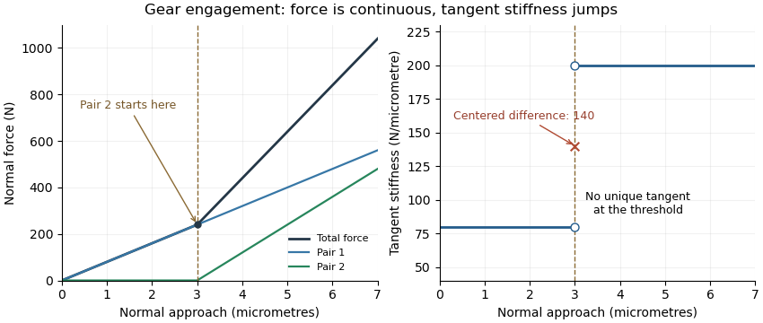
Original unilateral-contact model: continuous force, a gear tooth engagement threshold, and distinct one-sided gear mesh tangent stiffness values
. Details. The measured displacement channel also matters. If a contact stiffness is in series with support stiffness , their mechanical compliances add, givingA measurement spanning the whole assembly would therefore not isolate the contact stiffness.
For a perturbation experiment, report the mean load, mesh position, displacement endpoints and whether the increment crosses a contact transition. A primary NASA analysis used a coupled tooth-stiffness/dynamic-load calculation; the derivative above explains a local quasistatic limit, rather than replacing that dynamical model.[ref]
Gear sliding velocity is the relative tangential surface velocity at a tooth contact. It must distinguish the common point where the tooth surfaces touch from the two material points instantaneously occupying it. For an ideal fixed-axis external involute pair, relative normal velocity vanishes, but relative tangential velocity generally does not. It is zero at the gear pitch point and grows with distance from it along the gear line of action.[ref]
Elements of Metric Gear Technology by SDP-SI. §3.1, common base-circle tangent, line of action and pitch-circle geometry
Let be the pitch point, a contact point and a unit direction along the line of action. Use a common positive rotation axis for both signed angular velocities. The rigid-body velocity law givesSubtracting these expressions and using equal velocities at givesThe result is perpendicular to the common normal, as the contact constraint requires. External gears rotate in opposite directions, so the sliding-speed magnitude is , rather than their speed difference in magnitude.
For and , at the signed tangential sliding velocity is ; at it is . Both vanish at . Doubling both shaft speeds doubles gear sliding velocity at the same contact location, while leaving the ideal gear ratio unchanged. This connects geometry and running speed to gear sliding-friction loss. The formula concerns a two-dimensional spur gear contact; general three-dimensional contact requires the complete surface velocities and common normal.
The gear pitch point is where the gear line of action meets the line joining the gear centers. For a fixed-axis external involute pair, it is the tangency point of the operating pitch circles. The point is a geometric location in the mesh, rather than a material mark permanently attached to one tooth.[ref]
Elements of Metric Gear Technology by SDP-SI. §3.1, pressure-angle, line-of-centers and base-circle tangent geometry
Let the gear centers be separated by , with tooth counts . Their operating radii locate the pitch point atFor external signed angular velocities, . The two hypothetical material points occupying the pitch point therefore have the same instantaneous velocity. This is the local rolling without slipping property used to construct the operating pitch circles.
For an original example, use20 and40 teeth separated by . The pitch point is20mm from the first center and40mm from the second. With and , both surface velocities at that location have magnitude and the same direction. Ideal relative gear sliding velocity is zero there.
Elsewhere on the gear path of contact, the two tooth surfaces can slide even while maintaining the required normal contact condition. The pitch point remains fixed in this fixed-axis geometry, while successive tooth-contact points advance through the mesh. Whether the pitch point itself belongs to a particular usable contact interval depends on the available flanks; the geometric definition does not assert that every modified tooth profile physically contacts at that point.
The gear path of contact is the locus of actual tooth-contact points during an engagement. For a conventional external involute pair, its active part is a finite straight segment of the gear line of action. Its endpoints are set by the usable tooth flanks, rather than by the infinite geometric line alone. The part before the gear pitch point is the gear path of approach; the part after it is the gear path of recess in the stated direction of transmission.[ref]
KHK Gear Nomenclature. “Length of Path of Contact”, active line segment, approach and recess definitions
For a standard noninterfering external pair driven by gear1, let be tip radii, base radii, operating radii and the operating pressure angle. When tip circles bound the full usable contact,Adding gives . The two lengths need not be equal even when the gears use the same module and reference angle.
For the original module2,20/40-tooth example at20degree reference angle and60mm standard separation, tip radii22 and42mm give and . Their sum is ; dividing by gear base pitch gives transverse gear contact ratio about1.6352.
These are distances along the line of contact, not arc lengths traveled around a pitch circle. A shortened or altered flank can reduce the active interval, and interference can invalidate the full tip-limited construction. The labels approach and recess also depend on which direction is being followed. A practical contact inspection therefore needs the profile geometry and transmission direction, not just a sketch of two nominal pitch circles.
Gear contact duration is the time for a specified tooth pair to traverse its active gear path of contact. For a fixed-axis external spur gear pair at constant speed, the contact location advances along the gear line of action at the common gear base-roll speedThis is the speed of the contact location along a geometric line, not the relative tooth-surface gear sliding velocity. The latter vanishes at the gear pitch point, while the contact location continues moving. For active path length , duration is . The geometry relates gear contact ratio to active path length divided by gear base pitch.[ref]
The time between successive tooth-pair entries is , with gear mesh frequency . Since for compatible operating geometry, the base-circle distance advanced per entry isConsequentlyA contact ratio above1 means one pair remains engaged after the next pair enters; it does not mean one pair contacts for an entire shaft revolution.
For the standard module2,20/40-tooth example with20degree reference angle, active length is9.65457mm and base pitch is5.90426mm. At driving angular velocity , , and . The entry interval is6.28319ms, giving . Doubling both shaft speeds halves duration while preserving geometric gear contact ratio. Variable speed requires integrating the changing base-roll speed; a helical gear also needs a stated transverse slice or a whole-face contact convention.
Gear base-roll speed is the rate at which base-circle rolling advances an ideal involute contact along the gear line of action. For a fixed-axis external pair at constant speed,The equality follows from the tooth-count speed ratio and compatible base pitches. It describes the rate of change of contact position along a geometric line, rather than the gear sliding velocity between material points on the flanks. Base circles and their common tangent define this geometry.[ref]
KHK Gear Nomenclature. Basic Guide B §3, printed pp.20–21, involute/base-circle construction; “Length of Path of Contact”, active line-of-action segment
For standard module2 gears with20 and40 teeth at20degree reference angle, base radii are and . Signed angular velocities and give the same . The first gear's reference-circle tangential speed is1m/s, so base-roll and pitch-circle speeds are distinct.
In one tooth-entry interval, the base circle advances one gear base pitch:With , the example advances5.90426mm per entry. An active contact length9.65457mm therefore gives gear contact duration .
For compatible involute teeth, changing center distance changes the operating pressure angle and operating pitch circles, while leaving the manufactured base circles unchanged. At the same shaft speeds, base-roll speed is therefore unchanged even though the usable contact length may change. This separates a kinematic rate from the active interval needed to calculate contact time. If speed varies, contact displacement follows ; a constant-speed quotient is then only an approximation.
The gear path of recess is the part of the active gear path of contact followed after passing the gear pitch point, in the stated driving direction. For a standard external involute pair driven by gear1, contact ends at the driving gear's tip circle when that tip bounds the usable profile. The recess length lies on the gear line of action; it is not an arc of the gear pitch circle.[ref]
KHK Gear Nomenclature. “Length of Path of Contact”, recess segment from pitch point to final contact
Use driving-gear tip radius , base radius , operating radius and operating pressure angle . The base-circle tangent triangle givesFor a standard module2,20/40-tooth pair at60mm separation and20degree reference angle, , and yield . The corresponding gear path of approach is about5.0586mm, so the pitch point does not bisect the active contact interval.
At driving angular velocity , the contact-location speed is . Recess therefore lasts about4.891ms. Adding approach gives gear contact duration . Tooth-passage frequency is , so , agreeing with the transverse gear contact ratio calculated as active length divided by gear base pitch.
A shorter usable driving flank reduces recess and can change gear sliding-friction loss, because sliding grows with distance from the pitch point. The tip-circle formula alone cannot describe profile modifications or an interfering contact. The geometry and direction must be specified before applying the approach/recess labels.
The gear path of approach is the part of the active gear path of contact followed before the contact reaches the gear pitch point. For a conventional external involute pair in the stated driving direction, contact starts where the driven gear's tip circle intersects the usable gear line of action, and then moves toward the pitch point. This is a straight-line distance along the common normal, not an arc around a pitch circle.[ref]
KHK Gear Nomenclature. “Length of Path of Contact”, approach segment from first contact to the pitch point
Let gear1 drive gear2. Write for gear2's tip radius, for its base radius, for its operating radius and for operating pressure angle. A right triangle from the base-circle tangency gives tip-to-tangency distance . Subtracting the pitch-point-to-tangency distance givesThis formula assumes the full tip-limited interval is usable without interference or profile truncation.
For an original standard module2,20/40-tooth pair at60mm center distance and20degree reference angle, gear2 has tip radius42mm, operating radius40mm and base radius . Consequently . If gear1 rotates at , contact advances along the line at , giving an approach contribution to gear contact duration of about . This contact-location speed differs from gear sliding velocity, which tends to zero on arriving at the pitch point.
The total active length adds gear path of recess. Reversing the followed engagement direction exchanges which segment is called approach and which is recess. If altered usable flanks exclude the nominal pitch point, an assumed positive tip-limited formula must not replace an inspection of the actual active interval.
Gear efficiency is the fraction of mechanical input power delivered as useful mechanical output power over a stated operating condition and system boundary:For steady forward operation with positive input power, accounts for dissipation within that boundary. Tooth-contact friction is one contribution; a complete gearbox measurement can also include other rotating supports and lubricant losses. Citizen Micro explicitly treats its quoted stage efficiencies as reference values that depend on transmitted torque and speed.[ref]
Technical Data Gearhead by Citizen Micro. “Gear Efficiency”: mechanical losses and dependence on torque and speed
If the positive reduction gear ratio is , thenAn increase in torque therefore does not itself measure gear efficiency: reduction increases torque while decreasing speed. For an original example, let input torque be at revolutions per minute, and output torque be at revolutions per minute. Then andThe angular-speed conversion factors cancel in the ratio but must be included when computing power in watts.
A bench test places torque and rotational-speed measurements on both sides of the chosen transmission, compares synchronized measurements after reaching steady operation, and reports load, speed and temperature. During acceleration, a difference between input and output power can partly represent changing kinetic energy, rather than loss. Near zero useful load, approximately fixed losses can also produce a much smaller efficiency than at a loaded operating point. For successive stages with consistent boundaries and no extra power path, efficiencies multiply; three hypothetical stages yield , rather than .
A gear train is an interconnected arrangement of gears that transmits rotation through one or more meshes. Its behavior depends on which gears mesh and which are rigidly attached to the same rotating body. A simple gear train passes motion through successive individual gears; a compound gear train uses at least one intermediate rotating body carrying different gears rigidly together.[ref]
For a chain of external meshes on fixed parallel axes, each mesh satisfies . Multiplication gives the overall signed gear ratio; two rigidly joined gears instead share exactly the same angular velocity. These are different connection rules and must not be interchanged.
In a simple gear train with tooth counts 16, 40 and 64, the overall relation isThe intermediate count cancels, and the two reversals give equal input/output rotation directions. That intermediate gear can still change spacing and mounting geometry even though it does not change this reduction ratio.
For a compound gear train, let a 16-tooth input drive a 48-tooth gear, rigidly joined to a 12-tooth gear that drives a 60-tooth output. ThenAn input of revolutions per minute produces revolutions per minute at the output. The two intermediate tooth counts do not cancel because they belong to different gears sharing rotation, rather than one gear engaging both neighbors.
In steady operation, stage gear efficiencies multiply when all intervening losses are included in their stated power boundaries. If the two stages each have efficiency , the total is ; at input torque , the output torque is . These fixed-axis relations do not automatically describe arrangements whose gear axes move. In all cases, measured speeds test kinematics, while measured power is needed to establish losses.
A split-torque transmission divides transmitted load among two or more mechanical paths and subsequently combines their contributions. Its purpose is to let several meshes carry a total load that would otherwise pass through one path. The gear torque-path load fraction depends on compatibility, stiffness, gaps and mounting; a symmetric layout alone does not prove equal sharing.
For an original idealization, refer both branch torques to the same shaft coordinate and let their common elastic twist be . With torsional stiffnesses and no initial gaps,Values and under total torque give and branch torques and . If each branch were limited to , this sharing would limit total load to ; equal sharing would permit within the same simplified capacity assumptions.
Parallel-path gear efficiency also differs from the product rule for serial stages. If input power fractions are with , and each branch delivers fraction of its input power to the common output boundary, thenFor fractions and efficiencies , the result is . Multiplying the two branch efficiencies would describe a different arrangement of power boundaries.
The primary face-gear program reported input-pinion torque division about , while its two idlers shared about . These were measured results with stated calibration limitations, not exact consequences of the layout.[ref]
Development of Face Gear Technology for Industrial and Aerospace Power Transmission by Gregory F. Heath and others. Summary, printed p. iii; Conclusions, printed p. 84, torque splits and strain/load calibration limits
A meaningful load-sharing test measures both paths over relevant load and position ranges. Strain gauges need an appropriate measurement calibration because different tooth load distributions can produce different strain responses for the same transmitted load. Floating pinions provide one mechanism for reducing imbalance, but the complete assembly and its constraints still determine the operating split.
A gear torque-path load fraction specifies how a stated total transmitted torque is divided among paths of a split-torque transmission. With all branch torques referred to the same shaft coordinate,For positive total torque and nonnegative contributions, the fractions lie between zero and one and sum to one. If a path carries reverse or circulating power, the signed ratio requires a different interpretation; it need not lie in that interval.
The common coordinate is essential. Two branches carrying at and carry powers and . Their equal raw torques do not imply equal power shares. If ideal gearing brings both contributions to a common output speed , their output torques are and , giving fractions and .
For parallel elastic paths with the same twist coordinate and zero gaps, gives . In that model a stiffness ratio gives fractions and , regardless of the total torque while the same linear branches remain active. Gaps and a floating pinion can change that allocation.
A sensor ratio also needs a measurement model. If two channels obey and , thenEqual torques with sensitivities and give raw signals in the ratio ; the raw signal fraction is not the torque fraction . Cross-talk and changing tooth-load distributions may require a fuller calibration model.
The primary face-gear program reported approximately division at the input pinions and a different split between its idlers. The report also explains why tooth strain was not an invariant direct proxy for transmitted load.[ref]
Development of Face Gear Technology for Industrial and Aerospace Power Transmission by Gregory F. Heath and others. Section VIII, printed pp. 71–78; Conclusions, printed p. 84, torque calibration, reported splits and strain/load limitations
Report the reference shaft, sign convention, operating condition and measurement uncertainty with a torque-path fraction.A floating pinion has mounting freedom that permits a limited position adjustment between its mating meshes. The resulting force balance can improve load division in a split-torque transmission. Floating does not mean unsupported: bearing and shaft constraints still transmit loads, and the allowed displacement must match the intended balancing direction.
An original symmetric scalar model illustrates the mechanism. Let two opposed mesh reactions bewhere sets mean compression, represents an initial mismatch and is the pinion's balancing displacement. Assume both contacts remain compressed. Let floating-pinion centering stiffness provide support reaction , with the reaction sign chosen so that equilibrium is . ThenWith negligible centering restraint, and the reactions become equal. In the rigid-centering limit, and the original imbalance remains.
For stipulated , and , rigid centering gives forces and . Free adjustment gives and . At , displacement is and forces are and . These describe the chosen scalar model, rather than a complete face-gear support design.
The primary 2002 rig slow-rolled pinions between two face gears, applied loads through hanging masses, pulleys and cables, and used tooth-root strain gauges. Its cantilevered pinion mount allowed a balancing displacement.[ref]
Development of Face Gear Technology for Industrial and Aerospace Power Transmission by Gregory F. Heath and others. Summary, printed p. iii; Introduction, printed p. 1; Section VIII, torque calibration and split determination
The report's modified fixed-pinion comparison sent nearly all its load to one face-gear mesh, illustrating the effect of constraint in that tested assembly.[ref]Development of Face Gear Technology for Industrial and Aerospace Power Transmission by Gregory F. Heath and others. Conclusions, printed p. 84, fixed modified-idler comparison
Finite travel, friction, backlash or loss of one contact can prevent the ideal balancing solution. At low load, the condition that both model forces are nonnegative must be checked; a gear tooth engagement threshold can change the equations. Position freedom can help sharing without guaranteeing identical tooth stress or a perfectly equal torque split at every operating condition.
Floating-pinion centering stiffness describes the local restoring-force response of the mounting to displacement along a specified balancing coordinate. If mounting reaction is , a convenient positive restoring convention isFor , has force-per-length units. A rotational coordinate would require a torque-per-angle stiffness instead; the coordinate and displacement endpoints must be stated before comparing values.
In an original symmetric model of a floating pinion, two compressed mesh reactions obeyWith support reaction , equilibrium givesThe rigid-centering imbalance is , soBoth reactions must remain nonnegative for this two-contact model to apply.
For , and , choose . Displacement is and reactions are and . Raising to reduces displacement to but gives forces and . Stronger centering keeps the location closer to its reference while preserving more of the original imbalance.
Dynamic response is another question. With an effective mass and viscous coefficient , the same linearized floating-pinion balancing mode obeysIts undamped natural frequency is in angular-frequency units. A favorable static split does not by itself establish favorable dynamic behavior, and the toy mode does not include every shaft or housing motion.
A stiffness measurement should separate mounting reaction from the mesh reactions or report the combined assembly stiffness explicitly. The primary 2002 face-gear program used a cantilevered mounting to permit pinion balancing and examined a constrained comparison; it did not establish one universal centering stiffness for all transmissions.[ref]
Development of Face Gear Technology for Industrial and Aerospace Power Transmission by Gregory F. Heath and others. Introduction, printed p. 1; Conclusions, printed p. 84, floating mounting and modified fixed-pinion comparison
A floating-pinion balancing mode is a reduced mechanical motion in which a floating pinion shifts between mating meshes and redistributes their reactions. A one-coordinate model can connect the static balance set by floating-pinion centering stiffness with oscillation, damping and the possibility of losing a contact.
For two compressed linear contacts of stiffness , mismatch , support stiffness , effective mass and viscous damping coefficient , the illustrative equation isThe static position is . Setting givesFor , the oscillation frequency is and its amplitude envelope decays as . These frequencies have angular-frequency units; ordinary frequency is .
An original example uses , , and . It gives , , and an envelope reduced to after . With mismatch , the equilibrium displacement is . These are chosen model parameters, not measured gearbox constants.
A floating-pinion contact-loss check must still enforce the assumptions. For reactions and , both contacts remain compressed only while . If the oscillation leaves that interval, the two-contact linear equation must change; extrapolating a sinusoid into tensile tooth forces is inconsistent.
A motivating experiment perturbs the pinion slightly about a controlled loaded state, records its displacement and mesh-force proxies, and compares frequency and decay with the model while checking contact continuity. The primary face-gear report used slow rolling to study torque division and mounting freedom; it is evidence for that tested balancing arrangement, not a measurement of the hypothetical resonant frequency above.[ref]
Development of Face Gear Technology for Industrial and Aerospace Power Transmission by Gregory F. Heath and others. Introduction, printed pp. 1–2; test description and Conclusions, printed p. 84
A floating-pinion contact-loss check tests whether the motion predicted by a floating-pinion balancing mode remains compatible with every contact assumed to be compressed. It prevents a two-contact linear solution from being extrapolated into tensile tooth forces.
For the symmetric modelwith , mismatch , displacement and fixed mean approach , both contacts are compressed only whenAt equality one modeled force is zero. Outside the interval the linear expression makes one force negative; the unilateral model must replace that value by zero and the force-balance equations must be solved again.
Write and define the floating-pinion compression marginIf the motion satisfies , then is sufficient to retain both contacts. For a steady single sinusoid of amplitude and fixed , the maximum of over a complete cycle is , making the condition exact for that stipulated motion.
An original example uses , and . The margin is . A sinusoidal amplitude retains a minimum compression ; with , the smallest contact force is . Amplitude instead makes the unconstrained formula reach , revealing a contact-loss inconsistency rather than a physical tensile contact.
For a damped transient, an amplitude envelope is a sufficient bound but need not be attained at the phase where contact is least compressed. Failure of that sufficient envelope test therefore calls for examining the actual trajectory; it is not automatically proof that a real contact opened.
A controlled dynamic test can compare displacement with load-sensitive observations and check whether the assumed contact set persists. The historical face-gear program examined mounting freedom and torque division under slow rolling; it did not validate every possible dynamic contact assumption.[ref]
Development of Face Gear Technology for Industrial and Aerospace Power Transmission by Gregory F. Heath and others. Introduction, printed pp. 1–2; Conclusions, printed p. 84, floating versus constrained mounting
The floating-pinion compression margin is the amount of relative approach remaining before the less compressed contact reaches zero compression in a stated two-contact model. It turns the assumptions of a floating-pinion balancing mode into a quantitative admissibility check.
For and , let equilibrium position be and defineA positive means both contacts are compressed at equilibrium. If with , then guarantees compression throughout the bounded motion. For a steady single sinusoid and fixed , this is the exact full-cycle condition; a general transient envelope supplies only a sufficient bound.
An original nominal example has and , giving . A displacement amplitude passes that nominal check, leaving of minimum compression for the sinusoidal model.
A floating-pinion robust contact margin includes bounded parameter uncertainty. If and , a conservative lower margin isFor and , . The same amplitude is no longer guaranteed admissible, although failure of the bound does not prove contact loss. Amplitude leaves at least under these independent interval bounds.
In the symmetric static model, givesfor positive mesh stiffness and nonnegative floating-pinion centering stiffness . Mounting freedom can change the margin, but it also changes dynamics; maximizing this one scalar is not a complete gearbox design rule.
A floating-pinion contact-loss check must recompute the contact model once a force reaches zero. The historical face-gear tests provide evidence about mounting freedom and measured torque division under slow rolling, rather than a universal dynamic margin.[ref]
Development of Face Gear Technology for Industrial and Aerospace Power Transmission by Gregory F. Heath and others. Introduction, printed pp. 1–2; Conclusions, printed p. 84
A floating-pinion robust contact margin is the smallest two-contact compression margin allowed by a stated set of uncertain parameters. It strengthens a nominal floating-pinion compression margin by checking every admissible parameter combination, while retaining the assumptions of the underlying contact model.
Let be the common approach and the equilibrium imbalance in the symmetric linear model. If the admissible pairs form a set , defineFor displacement from equilibrium with , the smaller contact compression is at least . Thus guarantees positive compression for both contacts throughout the bounded motion. Equality permits zero compression and does not guarantee maintained compressive contact.
For independent interval bounds, or a bounding rectangle containing all possible pairs,This is exact when every pair in the rectangle is admissible. If the rectangle includes impossible combinations, it remains a conservative lower bound on .
A correlated floating-pinion uncertainty set can materially change the conclusion. In an original example, all quantities are in micrometres andHere stays positive, so for every allowed . The exact joint-set margin is . Treating the ranges independently instead gives . An amplitude passes the joint-set guarantee with residual compression , but fails the rectangular sufficient test. Failure of a conservative test does not itself demonstrate contact loss.
The admissible set must come from defensible parameter bounds, including any shared mounting or thermal effects. A covariance estimate alone supplies no absolute bound for all realizations. If the motion amplitude also depends on uncertain parameters, a direct bound on can preserve correlations that separate worst-case bounds discard.
Floating mounting was physically motivated by face-gear load sharing. NASA's primary report describes mounting freedom and slow-roll torque-division tests; those observations motivate the contact model, but do not validate every dynamic or uncertainty assumption above.[ref]
Development of Face Gear Technology for Industrial and Aerospace Power Transmission by Gregory F. Heath and others. Introduction, printed pp. 1–2; Conclusions, printed p. 84
Once a contact opens, a floating-pinion contact-loss check must use the appropriate changed force law.A floating-pinion affine uncertainty bound evaluates the minimum contact-compression margin when the approach and imbalance depend linearly plus a constant on bounded shared parameters. It gives an exact result for a box of uncertainty variables, while preserving the dependence those variables induce between physical quantities.
In the correlated floating-pinion uncertainty set, supposeAll uncertainty vectors in this box are assumed admissible. For the linear two-contact model, the floating-pinion robust contact margin is the infimum of over that box.
First resolve the absolute value:For any affine expression , its minimum is : choose each bounded variable with the sign opposing its coefficient. Applying this rule to the two branches givesThe branches can attain their minima at different parameter vectors. Taking the smaller of their independently attainable minima is valid; requiring both minima to occur at one vector would impose an unnecessary condition.
For an original example in micrometres, letThe two branch minima are and , so . The first is attained at . Treating the separate physical ranges independently instead gives and , hence a looser bound. A motion amplitude leaves guaranteed compression in the shared-variable model.
The result is exact for the stated box and affine model. Additional constraints can make it conservative; nonlinear parameter dependence or opening of a contact can invalidate the model itself. A floating-pinion ellipsoidal uncertainty bound addresses a different set shape, and a statistical covariance matrix alone does not certify a hard bound.
NASA's face-gear report supplies the physical motivation for examining mounting freedom and load sharing, not an experimental validation of these chosen uncertainty coefficients.[ref]
Development of Face Gear Technology for Industrial and Aerospace Power Transmission by Gregory F. Heath and others. Introduction, printed pp. 1–2; Conclusions, printed p. 84
A valid guarantee requires defensible parameter bounds and the appropriate floating-pinion contact-loss check.A floating-pinion ellipsoidal uncertainty bound gives the smallest two-contact compression margin when the uncertain parameter vector lies in a specified ellipsoid. It retains shared parameter effects, as does the floating-pinion affine uncertainty bound, but uses a different admissible-set shape.
Let approach and imbalance be affine functionsand describe the set by with . Put and . The floating-pinion robust contact margin then satisfies the exact formulaTo prove it, write . For either linear coefficient vector , the Cauchy-Schwarz inequality givesIf , equality is attained at . Thus the result supplies both a margin and an attaining direction. The image representation also handles rank-deficient sets without inverting a shape matrix.
For an original example in micrometres, take , the identity andOver , the two branch minima are and , so the margin is about . The first branch attains it at . The encompassing box instead gives because it admits combinations excluded by the disk.
A covariance-derived ellipse does not automatically certify an absolute engineering bound. Its probability content requires distributional assumptions and an appropriate radius; a hard guarantee requires a defensible admissible set. NASA's face-gear mounting and slow-roll load-sharing observations motivate the physical contact question, not the particular coefficients or set used here.[ref]
Development of Face Gear Technology for Industrial and Aerospace Power Transmission by Gregory F. Heath and others. Introduction, printed pp. 1–2; Conclusions, printed p. 84
The two-contact force law must also remain valid; contact opening requires the floating-pinion contact-loss check.A compound gear train has an intermediate rotating body carrying at least two rigidly joined gears. Those gears share angular velocity but can have different tooth counts, allowing successive reductions to multiply without the cancellation found in a simple gear train. For two external stages with the second and third gears rigidly joined,The two external meshes give equal input/output rotation directions.[ref]
For an original example, use tooth counts , , and . The reduction is . Input speed revolutions per minute gives intermediate speed and output speed revolutions per minute.
This example also permits a reverted gear train, with input and output axes coaxial. If both stages use the same gear module and standard unshifted spur gears, the two axis separations must agree:Here both tooth-count sums equal72, so gives a common separation . Ratio multiplication alone would not establish this packaging condition.
In steady ideal operation, output torque is fifteen times input torque. With stage gear efficiencies , it becomes times input torque, provided the stage power boundaries include the stated losses. A high reduction can therefore trade compact stages against added losses, loads and backlash. Axis separations and support loads remain separate requirements from the desired numerical gear ratio.
A reverted gear train returns the output rotation axis to the input axis, usually through a two-stage compound gear train. The input and output gears can rotate independently on coaxial shafts, while the intermediate gears share another rotating body. Coaxial axes are a layout condition in addition to the desired gear ratio.
For standard unshifted spur gears, let gears1 and2 mesh in the first stage and gears3 and4 in the second, with2 and3 rigidly connected. The common intermediate-axis separation requiresIf both stages use the same gear module, this reduces to . The reduction ratio independently satisfies . Both conditions must be satisfied; multiplying arbitrary stage ratios does not ensure a reverted layout.[ref]
For an original design example, choose counts20,60,16 and64, with module in both stages. Both sums are80, so both separations are . The reduction is , taking an input of1440 revolutions per minute to an output of120. Two external meshes give the same input/output rotation direction.
The gears occupy different axial planes so that coaxial input and output do not require them to be one rigidly joined gear. A practical design still needs independent shaft support, compatible tooth geometry in each stage and adequate clearances. Operating with shifted tooth geometry or another mounting changes the applicable separation equations; the simple tooth-sum condition belongs to the stated standard-gear model.
A simple gear train transmits rotation through individual intermediate gears, each intermediate gear engaging its neighbors without a separate, differently sized gear rigidly sharing that intermediate rotation. For external meshes on fixed parallel axes, consecutive signed ratios multiply and intermediate tooth counts cancel:where is the number of external meshes. An intermediate idler gear changes placement and potentially output direction, but not this ideal endpoint tooth-count ratio.[ref]
KHK Gear Nomenclature. Basic Guide B, §1.1, pp.4–5, fixed-axis external mesh ratios and gear-train connections
For example, a chain with tooth counts 18, 30, 42 and 72 has three meshes andAt input speed revolutions per minute, output speed is revolutions per minute in the opposite direction. Removing one intermediate gear while maintaining a compatible two-mesh layout preserves the fourfold reduction but reverses the direction conclusion.
The cancellation concerns kinematics, not every engineering consequence. Intermediate tooth counts affect physical sizes, axis positions and angular speeds of intermediate rotating bodies; additional meshes and supports can change gear efficiency and backlash. Moreover, if two different intermediate gears are rigidly coupled, their tooth counts do not cancel by the same argument: that arrangement is a compound gear train.
An idler gear is an intermediate gear that passes rotation between other gears without using a separately sized, rigidly coupled gear to form another reduction stage. In a simple gear train, its tooth count cancels from the ideal endpoint ratio, but it changes placement, intermediate speed and the number of direction reversals.
For example, a20-tooth input driving a30-tooth idler gear that drives a50-tooth output givesAt750 input revolutions per minute, the idler turns at500 in the opposite direction and the output at300 in the original direction. Replacing the idler by60 teeth preserves output speed but changes idler speed to250 revolutions per minute.[ref]
With standard module and collinear centers, the30-tooth idler gives input/output axis spacingThe60-tooth replacement gives190mm, despite the unchanged output ratio.
An idler support reaction also remains necessary even when its net transmitted torque is zero. For the30-tooth arrangement, suppose input torque is , so both ideal mesh tangential loads are . Their moments about the idler's center cancel, but in this collinear layout the two tangential forces point in the same direction on the idler. Equal, opposite radial mesh components cancel, leaving a mesh-induced shaft-support reaction of opposite the tangential forces.
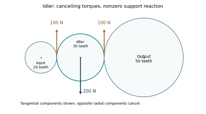
The drawing shows tangential mesh components and their balancing support reaction, rather than physical tooth profiles. Additional shaft loads are outside this ideal balance. The idler therefore affects geometry, forces and potential losses even though its count cancels from the ideal speed ratio.
An idler support reaction is the force exerted by the shaft and bearings that balances the mesh loads and other external loads on an idler gear. A vanishing net transmitted torque does not imply a vanishing resultant force: moments can cancel while forces add. A free-body diagram must retain each tooth-contact force and its point of application. The tangential load in each ideal mesh follows from .[ref]
Elements of Metric Gear Technology by SDP-SI. §7, gear forces; tangential transmitted load and pressure-angle separation of mesh forces
Consider a steady collinear train with input, idler and output reference radii20,30 and50mm. An input torque gives a100N tangential mesh component. On the idler, choose contact positions at and relative to its center, with both tangential forces upward. Their moments are and , but their vector sum is200N upward. For equal20degree pressure angles, the two radial mesh components have magnitude and opposite directions, so they cancel. Neglecting other loads, the net support reaction is200N downward.
This is the combined support resultant, not automatically the load on each bearing. For a hypothetical shaft supported at axial positions and , with the200N upward gear resultant acting at , static equilibrium givesThus and . Idler bearing load sharing depends on placement even when the total reaction is fixed.
Noncollinear shaft layouts rotate the mesh-force directions, and helical gears add gear axial force. Acceleration also changes the balance: the sum of torques must supply the idler's angular acceleration, and unequal mesh loads need not cancel radially. The zero-net-torque example therefore establishes a steady ideal force balance, rather than a universal bearing-load formula.
Idler bearing load sharing determines how an idler support reaction is divided among the shaft's supporting bearing elements. Zero net torque on an ideal steady idler gear does not remove its mesh-induced transverse force. The bearing loads additionally depend on axial positions and the supported-shaft arrangement. Manufacturer guidance separates a radial load between two bearings from an overhung load and treats gear loads as applications of those cases.[ref]
Model the shaft as a simply supported beam with supports A and B at axial coordinates and . Let a gear resultant act upward at , and take upward reactions as positive. Static equilibrium requiressoFor a200N mesh resultant at between supports100mm apart, the downward reactions are120N and80N. Equal division occurs only for the centered load in this symmetric ideal support model.
For overhung idler loading at with the same support span and resultant, and . The farther support's force reverses direction, and the nearer bearing carries more than the applied resultant. This does not violate force balance: . If a particular support cannot provide the required reaction direction, the assumed support model must change.
For loads in two transverse directions, solve each component balance before forming the resultant at each bearing. Helical gears add gear axial force; allocating that thrust requires the actual bearing constraints and cannot be inferred from the transverse lever rule. More than two effective supports generally require deformation compatibility as well as equilibrium. These calculations estimate support forces, rather than directly determining bearing life or internal rolling-element contact loads.
Overhung idler loading occurs when an idler gear's mesh resultant acts outside the axial span of its shaft supports. The overhang creates a lever arm, so the nearer mechanical bearing can carry a larger transverse load than the mesh resultant and the farther support can have the opposite reaction direction. This geometry is separate from whether the idler's two transmitted torques cancel.[ref]
Place ideal radial supports A and B at and . An upward mesh resultant at , with overhang , gives static equilibriumHenceFor , and , A acts upward with60N while B acts downward with260N. Their signed sum balances the applied200N. The larger reaction at B is a lever effect, not an additional external mesh force.
The overhung shaft bending moment immediately next to the near support has magnitude in this ideal model. That bending moment can exist while the net shaft-axis torque on the steady idler is zero. Doubling overhang at fixed load doubles the near-support bending moment and changes the reaction magnitudes to120 and320N.
Idler bearing load sharing must therefore include the gear's axial position, not just its pitch radius and speed ratio. Loads in independent transverse directions can be balanced separately and then combined as vectors. A support model with more constraints requires compatible deformations as well as force balance. Shaft bending and support flexibility can also alter the gear face load distribution, linking the overhang geometry to tooth loading.
An overhung shaft bending moment is the internal bending moment produced when a transverse load acts beyond the shaft's support span. For a single end load at overhang distance , its magnitude immediately next to the nearer support isin the ideal two-support shaft model. The relevant lever arm is the distance beyond that support, rather than the distance between supports. Manufacturer bearing-load guidance distinguishes this arrangement from a load located between bearings.[ref]
Place ideal supports A and B at axial positions and , and apply an upward load at . With upward reactions positive, static equilibrium givesChoosing the internal moment sign consistently with the left-hand force sums, the bending moment along the shaft isIt is continuous at B, reaches there and vanishes at the free end. An ideal bearing need not apply a concentrated couple for the shaft's internal moment at its location to be nonzero: the shaft continues beyond that support.
For original values , and , the reactions are and and the peak moment is . Doubling at fixed doubles that moment. Changing while keeping fixed changes the reactions but leaves unchanged.
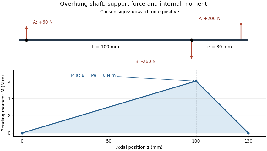
For a uniform solid circular shaft in simple elastic bending, overhung shaft bending stress follows from and :At diameter , the example gives about . This excludes stress concentrations and other loads; a shaft's allowable load requires more than this nominal estimate. Bending can remain even when opposing gear torques give zero net shaft-axis torque, because transverse-force moments and axial twisting are different components of the mechanical loading.
Overhung shaft bending stress is the longitudinal normal stress caused by the bending moment from a transverse load beyond the shaft's supports. It differs from twisting due to shaft-axis torque. In the ideal two-support model, the largest overhung shaft bending moment has magnitude , where is the end load and the overhang.[ref]
For a homogeneous linear elastic beam, plane sections in the beam model give longitudinal strain relative to the neutral axis. With Young's modulus ,where is the second moment of area. Thus . For a solid circular shaft of diameter , and the outermost distance is , givingAn original example uses , and . Then and . Reducing diameter to multiplies nominal stress by , raising it to about . The cubic diameter dependence makes a diameter change different from an equal percentage change in overhang.
A measurement check can place opposed axial strain gauges at one shaft station. In a simple axial-plus-bending model, readings and microstrain give axial strain microstrain and bending strain microstrain. This separates two contributions that a single gauge would mix.
The nominal formula excludes local geometric concentrations, multiaxial loading and yielding. It is not a fatigue-life prediction. Under a stationary bending direction, a rotating material point can experience alternating stress, motivating rotating shaft bending fatigue even when the external load is steady. A permissible load requires the actual geometry, material and load history.
A spur gear is a cylindrical gear with straight teeth parallel to its rotation axis. A conventional external pair transmits motion between parallel axes. Unlike the inclined teeth of a helical gear, the ideal straight-tooth geometry produces no axial thrust from the tooth-normal contact force; there are still tangential and separating loads that the mounting must carry.[ref]
KHK Gear Nomenclature. The ABC's of Gears, Basic Guide B, §1.1, printed pp.4–5, straight spur teeth and comparison with helical gears
For compatible spur gears, reference diameter is , where is gear module and is tooth count. Standard reference axis separation is . Two external spur gears have signed angular velocity relation : they rotate in opposite directions. Matching gear module alone is insufficient; tooth profiles and gear pressure angles must also be compatible.
For an original example, take gear module and tooth counts 20 and 60. Reference diameters are and , so standard axis separation is . Driving the smaller spur gear at revolutions per minute gives the larger one revolutions per minute in the opposite direction. In a steady ideal transmission, an input torque of becomes at the output. The corresponding input gear tangential force is ; multiplying this same force by the output reference radius recovers the output torque.
A simple bench demonstration marks one tooth on each spur gear and counts complete turns, testing the three-to-one gear ratio. Measuring transmitted torques and rotational speeds additionally tests gear efficiency. Observing the rotation ratio alone cannot establish a tooth's allowable load or the losses caused by friction and backlash.
The gear module specifies the size of metric gear teeth through the gear reference circle. For a spur gear with reference diameter and teeth,The tooth count is dimensionless, so gear module has units of length, conventionally millimetres. A larger gear module means a larger reference diameter at fixed tooth count. It does not mean a larger gear ratio, which depends on the tooth counts of the meshing pair.[ref]
The gear circular pitch is the arc length between equivalent points on adjacent teeth, measured along the gear reference circle. Dividing the circumference by the tooth count givesFor example, a spur gear with and has reference diameter and gear circular pitch . A 48-tooth gear of the same gear module has diameter but the same tooth spacing. Their standard axis separation is , and their reduction gear ratio is .
Conversely, two gears can have the same diameter without compatible tooth spacing: can describe 24 teeth of gear module or 18 teeth of gear module . Such teeth do not form the specified standard pair. For ordinary compatible spur gears, matching gear module is necessary but does not by itself specify the complete tooth geometry: the gear pressure angle and other tooth details must also agree. The definition uses reference diameter, not the diameter through the tooth tips or the operating pitch circle of a particular mounting.
Gear circular pitch is the arc distance between corresponding points on successive gear teeth, measured on the gear reference circle. If that circle has diameter and tooth count , its circumference contains repetitions, givingwhere is gear module. The length is measured along the reference arc, rather than as a straight chord between tooth positions.[ref]
For a spur gear with and , reference diameter is , gear circular pitch is , and angular tooth spacing is . The corresponding chord on the reference circle isThe small numerical difference matters when a dimensional inspection is intended to measure reference arc spacing. Increasing the tooth count while holding gear module fixed enlarges the gear reference circle but preserves gear circular pitch.
For an involute tooth profile, the gear base circle provides another spacing, the gear base pitch. Since , with reference gear pressure angle ,At , the preceding example gives . Compatible contact must preserve the spacing of successive tooth flanks along their gear line of action; this explains why equal gear circular pitch with incompatible gear pressure angles is not enough to specify a mating pair. Tooth thickness and backlash are additional quantities: gear circular pitch includes an entire tooth-and-space repetition.
Gear base pitch is the spacing of successive involute tooth profiles referred to the gear base circle. For base diameter , tooth count , gear module and reference gear pressure angle ,It also gives the spacing between successive corresponding tooth contacts measured along the gear line of action. The gear circular pitch uses the reference circle instead, giving and .[ref]
For and , but . A second gear with the same module but reference angle has . Matching reference tooth spacing alone therefore does not make these the same specified mating geometry.
Changing the mounting separation of a compatible involute pair does not change its cut profiles, base circles or gear base pitch. In operating-circle notation, changes with mounted radius, whilestays fixed. This links the mounted operating pressure angle to an invariant tooth-profile spacing.
For a tooth rotating at angular speed , base-circle tangential speed is . Dividing by gear base pitch gives the gear mesh frequency,A 30-tooth gear at revolutions per minute gives . Finally, the gear contact ratio divides usable gear path of contact length by this base pitch, so profile spacing and available contact length jointly determine overlap between successive tooth engagements.
A gear ratio states the relation between the rotational motions of connected gears. Because conventions differ, specify the input, output and direction. Here the positive reduction ratio isso means that the output has lower angular speed. For a single external pair on fixed axes, tooth-passage counting givesThe minus sign assumes the same positive rotation convention on both parallel axes. KHK uses the driven-to-driver tooth-count ratio for its speed-reduction examples.[ref]
Ratios multiply through successive stages of a gear train. Consider a 12-tooth input driving a 36-tooth gear, with a 15-tooth gear rigidly attached to that intermediate rotating body and driving a 45-tooth output. Each stage reduces angular speed by three, so the combined reduction ratio is nine. An input of revolutions per minute yields an output of revolutions per minute. Two external meshes reverse direction twice, so input and output rotate in the same direction.
An intermediate gear used only to pass rotation onwards gives a different result. If a 12-tooth input drives a 36-tooth intermediate gear that itself drives a 48-tooth output, the ratio is : the intermediate tooth count cancels. The previous ninefold reduction required two distinct tooth counts rigidly sharing the intermediate rotation.
For steady ideal transmission, conservation of energy gives . If gear efficiency is , the corresponding relation is . With , and input torque , the output torque is . This power balance assumes steady operation: accelerating rotating components can temporarily store kinetic energy. A measured gear ratio establishes kinematics, while torque capacity and losses require additional mechanical information.
A gear pitch circle is an imaginary circle used to represent the motion or reference geometry of a gear. A useful distinction is between the gear reference circle, specified for an individual gear, and the operating pitch circle, determined for a meshing pair. The terminology entry in KHK Gear Nomenclature calls the latter the intermeshing pitch circle and also uses the name working pitch circle.[ref]
KHK Gear Nomenclature. “Intermeshing Pitch Circle”, definition and alternative names; The ABCs of Gears, A, §7, printed p. 18: reference-circle diagram
For an external pair with fixed axes and constant gear ratio, imagine two operating pitch circles in contact and rolling without slipping. If their radii are and their axis separation is , their geometry and signed angular velocities obeyThe last equality follows by matching the gear ratio to tooth counts . It is an ideal kinematic construction: the imaginary circles themselves are not physical rims carrying the contact force.
For standard unshifted straight-tooth gears at their standard axis separation, the gear reference circles coincide with the operating pitch circles. The gear module specifies reference diameter . With and tooth counts 20 and 40, the reference diameters are and , giving reference radii and and standard separation . The reference diameters differ from the larger tooth-tip diameters. If a compatible pair is operated at another axis separation, its gear reference circles remain properties of the individual gears, while its operating pitch circles must fit the new separation and the same tooth-count ratio. This is why an unspecified “pitch diameter” should not silently mix reference geometry with operating geometry.[ref]
KHK Gear Nomenclature. “Calculation of Gear Dimensions”, §4.1, operating pitch circles of meshing profile-shifted spur gears; “Basic Gear Terminology and Calculation”, reference diameter
The operating pitch circles of two meshing gears are the imaginary circles that reproduce their motion by rolling without slipping. They are properties of the working pair and its mounting, whereas a gear reference circle specifies one gear's nominal geometry. Working pitch circle and intermeshing pitch circle are alternative names.[ref]
Consider an external pair of spur gears on fixed parallel axes, with axis separation and tooth counts . Their operating radii must satisfy both contact geometry and the tooth-count gear ratio:Solving givesThus the operating radii scale with the actual separation, while the gear ratio stays fixed by tooth counts. These are kinematic equations, conditional on the teeth actually maintaining compatible contact.
For an original example, choose gear module and tooth counts 20 and 40. Reference radii are and ; their standard separation is . If a compatible mounting uses instead, operating radii become and . At input angular velocity the output has , and both operating tangential speed magnitudes are . Using the reference radii in that speed calculation would incorrectly give .
For tooth flanks formed as involutes, the fixed gear base circles permit constant-ratio motion over a range of separations. If their radii are , the common-normal geometry giveswhere is the operating pressure angle. Increasing separation therefore increases that angle, while leaving each gear reference circle and gear base circle unchanged. This geometric possibility does not guarantee adequate tooth contact, clearance or strength at an arbitrary separation: the physical tooth extents and mounting must still be checked.[ref]
KHK Gear Nomenclature. The ABC's of Gears, Basic Guide B, §§3–4, printed pp. 20–23: involute geometry, base circles and changes of working pressure angle with axis separation
The operating pressure angle is the gear pressure angle of an actual meshing pair at its mounted axis separation. For external spur gears with involute profiles, it is the angle between the gear line of action and the common tangent to the operating pitch circles. Changing the separation changes this angle even though the individual gear base circles remain fixed.[ref]
Let the two base radii be and the mounted axis separation be . The right-triangle geometry of the gear line of action givesIf is the reference separation and both reference gear pressure angles equal , then , henceThe gear reference circles and gear ratio remain unchanged by this mounting adjustment; the operating pitch circles expand or contract to fit .
For example, reference radii and with give . Mounting a compatible pair at givesAt an imposed gear tangential force , the associated gear separating force is about , compared with at the reference angle. Holding torque instead of tangential load would additionally require using the changed operating radius.
The angle formula is only a geometric condition. Usable tooth flanks must still reach the contact region and maintain an adequate gear contact ratio; excessive separation can destroy useful contact. Likewise, the existence of a real inverse cosine does not establish that a proposed mounting has suitable backlash or mechanical strength.[ref]
KHK Gear Nomenclature. The ABC's of Gears, Basic Guide B, §4, printed pp.22–23, axis separation, working pressure angle and contact-ratio limits
A gear reference circle is the imaginary circle used to specify an individual gear's tooth geometry. For a spur gear, its diameter is defined by gear module and tooth count through . It supplies a common datum for tooth spacing and other dimensions, whether or not that gear is currently meshing with another one. The operating pitch circle, in contrast, describes the mounted pair's motion.[ref]
For a 30-tooth spur gear with gear module , the reference diameter is . Thus successive teeth repeat at an angular interval of and a gear circular pitch of on that circle. In the standard full-depth, unshifted geometry specified by KHK, the tooth-tip diameter is , giving in this example. Measuring the outside diameter and calling it the reference diameter would therefore produce the wrong gear module.[ref]
The gear base circle is another distinct geometric datum. For a tooth profile constructed as the involute of a circle, the gear base circle generates the curved tooth flank, whereas the gear reference circle fixes its nominal sizing. Their diameters obey , with reference gear pressure angle . With and , the base diameter is approximately . These three diameters—base, reference and tip—answer different questions about the same physical gear.[ref]
A gear base circle is the fixed circle from which an involute tooth flank is generated. Imagining a taut string unwinding from that circle, the free end traces the involute. It is a geometric construction for the tooth shape, distinct from the gear reference circle used for sizing and the operating pitch circle describing a particular meshing pair.[ref]
For base radius and unwinding parameter , one orientation of the involute isSquaring and adding gives . The local pressure-angle relation therefore gives . At the gear reference circle, this becomesFor reference diameter and reference gear pressure angle , the base diameter is , approximately. A change in mounting separation does not change this base diameter or the cut tooth profile; it changes which operating geometry describes the mesh.
In a compatible external pair, a common tangent to the two gear base circles is the gear line of action. Their fixed geometry gives , explaining why the operating pressure angle changes when changes. Repeating a tooth profile every also gives gear base pitch along the base circumference. Finally, an ideal involute generated this way lies on or outside its gear base circle; a real tooth's lower connecting portion can have a different shape. The gear base circle is not a physical boundary of the gear material.
Articles by others on the same topic



"Gear" can refer to different concepts depending on the context: 1. **Mechanical Gear**: In mechanics, gear refers to a rotating part of a machine with cut teeth or cogs that mesh with another toothed part to transmit torque and rotational motion. Gears are fundamental in various mechanical systems, helping to control speed, direction, and torque. 2. **Clothing and Equipment**: In everyday language, "gear" often refers to equipment or clothing used for a specific activity.