The gear pressure angle specifies the direction of tooth-normal contact relative to tangential motion. For an external spur gear pair with involute tooth flanks, its operating value is the angle between the gear line of action and the common tangent to the operating pitch circles. The gear line of action is the common normal to the contacting flanks and a common tangent to their gear base circles. Reference gear pressure angle and operating pressure angle coincide at the corresponding reference mounting, but need not coincide at another axis separation.[ref]
Elements of Metric Gear Technology by SDP-SI. §3.1, definition of pressure angle relative to line of action and line of centers
Neglecting friction, let the tooth-normal force magnitude be . Its components areThe gear tangential force transmits torque, , at operating radius . The gear separating force pushes the gear centers apart in the external mesh and loads their supports. Increasing gear pressure angle increases this separating load for the same transmitted tangential load.
For an original example, a spur gear transmits at . Then . At ,If the angle were at the same , the separating load would rise to approximately . This comparison concerns load direction, not gear efficiency: an ideal normal force can transmit power without dissipating it. Actual frictional contact adds another force component and can alter both losses and support loads.
Gear separating force is the component of an external gear mesh load along the line joining the gear centers, tending to push those centers apart. For a frictionless external spur gear pair,where is tooth-normal force, is gear tangential force and is operating pressure angle. This component acts on the shaft supports even when the mesh is ideal and lossless.[ref]
For example, take operating radius and transmitted torque . Then . At , ; at and the same tangential load, . The larger separating load is a change in load direction, not by itself an efficiency loss.
If the gear centers are ideally fixed, this radial component produces no work through a center-separation displacement, since that displacement is zero. Flexible supports can nevertheless deflect under it and store elastic potential energy. The resulting change in axis separation can change operating pressure angle, backlash and tooth contact, so the assumed geometry and support stiffness interact.
A support-load experiment can apply a known torque slowly to a mounted external pair and measure the reaction along the line of centers while maintaining the stated axis separation. Agreement with tests the force resolution under low-friction assumptions. Additional reactions, tooth friction and mounting preload must be accounted for before identifying a measured support force with this mesh component. Internal meshes and nonparallel-axis gearing require their own direction conventions; the external separating-force picture must not be transferred unchanged.
Gear tangential force is the pitch-circle-equivalent force that transmits torque in a gear mesh. At operating pitch radius ,For an external spur gear pair without tooth friction, it is the component of tooth-normal force along the common tangent to the operating pitch circles: . Together with the gear separating force, this resolves the mesh load in fixed shaft-loading directions. It is not a claim that the moving contact point always has that same local radial/tangential frame.[ref]
The relation follows geometrically from the gear line of action. Its distance from a gear center is the gear base circle radius , so the moment of a normal force is . Since , substitution yields .
For an original example, a 20-tooth input with operating radius transmits . Its gear tangential force is . Driving a 60-tooth output at operating radius ideally gives : the pitch-circle-equivalent tangential load is the same, while its moment arm is three times larger. At input angular speed , pitch speed is and transmitted power is , agreeing with .
The calculation assumes steady ideal force transmission. Gear efficiency affects the input/output power balance, while inertia can contribute additional torque during acceleration. A gear tangential force is also not the entire contact load: at , corresponds to normal load about and separating load about .
The gear line of action is the common normal along which ideal tooth contact transmits force. For meshing involute profiles in a transverse plane, it is a straight common tangent to the two gear base circles. The angle it makes with the common tangent to the operating pitch circles is the operating pressure angle.[ref]
Its intersection with the line of gear centers is the gear pitch point. The actual contact point moves along only a finite portion, the gear path of contact, bounded by usable tooth profiles. Thus a diagram's infinite straight line is a geometric construction, not a claim that teeth can contact everywhere on it.
The geometry explains constant ratio. Let the tooth-normal force magnitude be and the base radii . The perpendicular distance from each gear center to the gear line of action is its base radius, so the ideal transmitted moments have magnitudesThese moment arms do not change as the contact point advances along that line. The no-penetration contact condition correspondingly gives for an external pair. Compatible profiles have , recovering the tooth-count gear ratio.
For example, reference radii and at reference gear pressure angle give base radii approximately and . A normal force produces moment magnitudes and . Their ratio stays two as the point of contact moves.
Ideal normal transmission does not eliminate gear tooth sliding. Relative surface slip generally changes along the gear path of contact and vanishes at the gear pitch point for the ideal external pair. Actual friction associated with that slip adds a tangential contact force; its resultant need not lie exactly on the geometric gear line of action.
Gear tooth sliding is relative tangential motion of mating tooth surfaces at their contact point. Ideal contact prevents relative normal penetration but does not generally require the tangential surface velocities to agree. For a fixed-axis external involute pair, tangential slip vanishes at the gear pitch point and changes as the contact moves along the gear path of contact.[ref]
Let be the pitch point, let be a unit vector along the gear line of action, and write a contact location as . With a common positive axis and signed angular velocities , rigid-body velocity differences giveThe velocities at cancel, leaving this term proportional to distance along the contact line. Since has opposite sign in an external pair, the sliding-speed magnitude is .
For an original example, use and . At , gear sliding velocity along the common tooth tangent is ; at it has the opposite sign. At it is zero. Equality of operating pitch-circle speeds must therefore not be used to conclude that the tooth flanks roll without slipping throughout engagement.
In a simplified Coulomb friction model with coefficient of friction and normal load , the dissipated gear sliding-friction loss is . Hypothetical values , and give . This is a local illustrative loss model, not a lubricant specification. Zero ideal sliding at the pitch point also does not eliminate every source of gearbox loss, such as support friction or deformation-related dissipation. Real load and friction can vary through the engagement, so total loss requires integrating the applicable contact model.
Gear sliding-friction loss is the rate at which relative tooth-flank sliding dissipates mechanical energy. In a simple Coulomb friction model with normal contact load , coefficient of friction and gear sliding velocity , the nonnegative dissipated power isThis is a local contact model, rather than the entire gearbox loss. Manufacturer guidance distinguishes gear-meshing losses from losses in rotating supports and warns that overall gear efficiency depends on load and speed.[ref]
Technical Data Gearhead by Citizen Micro. “Gear Efficiency”, meshing/support losses and load- and speed-dependent efficiency
To derive the sign, let along the common tangent. The friction force on surface1 is and that on surface2 is . Their combined mechanical power is . The corresponding positive quantity is the rate of mechanical energy loss. At zero sliding the ideal Coulomb sliding-loss term vanishes, even though another resistance mechanism can remain.
For a fixed-axis external spur gear pair with , gives . Hypothetical and give . Holding these load and friction assumptions fixed while doubling both shaft speeds doubles the instantaneous loss at that geometric point.
Gear friction work per engagement integrates this varying loss through the active gear path of contact. If one pair carries a constant , the contact coordinate runs from to at constant speed , givingFor , and , the preceding loads and speeds give about . Real tooth pairs share varying loads; an overall loss calculation must sum the applicable contacts and integrate their actual loads, sliding and friction model.
Gear friction work per engagement is the mechanical energy dissipated by sliding during one tooth pair's active engagement. It is the time integral of that pair's gear sliding-friction loss:The result has units of joules, whereas instantaneous loss has units of watts. It excludes other gearbox losses such as support friction. Manufacturer efficiency guidance distinguishes meshing and support losses and emphasizes their dependence on operating conditions.[ref]
Technical Data Gearhead by Citizen Micro. “Gear Efficiency”, meshing/support losses and load- and speed-dependent efficiency
For a fixed-axis external spur gear pair, let signed contact coordinate run from to through the gear pitch point. Gear sliding velocity has magnitude . At constant shaft speeds, gear base-roll speed gives in this chosen direction. If and the force carried by this pair are constant,With hypothetical , , angular-speed sum75rad/s, , and , this gives about9.32mJ. Doubling both shaft speeds doubles instantaneous power but halves gear contact duration, leaving this idealized work per engagement unchanged. Real friction and load can themselves change with speed.
Gear tooth load sharing is essential when several pairs engage simultaneously. A constant total mesh load is not a constant full load on each active pair. If identical pair events recur at gear mesh frequency , averaging their correctly modeled losses over many events gives . The event's force history must already include load sharing; assigning the whole mesh load independently to every overlapping pair would overcount transmitted load and loss.
Gear tooth load sharing is the division of transmitted mesh load among simultaneously contacting tooth pairs. Gear contact ratio determines how engagement intervals overlap, but it does not by itself specify each pair's force. Tooth and support deformation, profile geometry and operating speed affect that distribution. A primary dynamic analysis explicitly coupled tooth stiffness with calculated dynamic loads rather than assigning a fixed full load to every active pair.[ref]
An illuminating quasistatic model treats active pairs as parallel springs with a common normal approach . With pair stiffnesses and no gaps, , soThe stiffness sum is gear mesh stiffness, and is a gear tooth load fraction. If two active pairs have stiffness100 and150N/µm under total normal load1000N, their common approach is4µm and loads are400 and600N. Equal sharing requires equal effective stiffness in this particular model.
Include a geometric gap by writing . If the second pair has a2µm gap, the same1000N total load gives with measured in micrometres. The result is , and . At only100N, the first pair alone compresses1µm, leaving the second pair out of contact.
For an ideal spur gear mesh with transverse contact ratio between1 and2, the fraction of a tooth-entry cycle having two pairs in contact is . A ratio1.635 therefore gives about63.5% two-pair contact and36.5% single-pair contact. This is geometric timing, not a guarantee of equal forces in the overlapping part. A gear friction work per engagement calculation must use each pair's own load history; dynamic motion can require more than the quasistatic spring approximation.
The gear tooth load fraction is the fraction of a stated total mesh force carried by tooth pair at a particular contact position or time:For nonnegative forces resolved in the same direction, and . A normal-force fraction must not mix one pair's normal load with another convention's tangential total. At zero total load the ratio is undefined.
An original quasistatic model treats engaged pairs as parallel springs with the same normal approach . If and every pair has zero initial gap, thenTwo pairs with stiffnesses and under total load approach by and carry and . Their fractions are and , rather than one half each. Counting two geometrically overlapping contacts does not establish equal gear tooth load sharing.
An initial gap changes the model toA pair below its gear tooth engagement threshold carries no load in this unilateral model. Changing total load can change both the active pairs and their fractions, even if all the individual stiffnesses remain constant. Gear contact ratio specifies geometric overlap; load fractions require deformation and engagement information.
The fractions also prevent double counting. If total load is , assigning that full load to both of two pairs gives an impossible sum of within this model. A gear friction work per engagement calculation must use each pair's own before summing its dissipation.
Dynamic motion can alter the quasistatic distribution. A 1986 NASA analysis calculated tooth stiffness and loads as contact position and speed varied, using a coupled stiffness/load iteration.[ref]
Predicted Effect of Dynamic Load on Pitting Fatigue Life for Low-Contact-Ratio Spur Gears by David G. Lewicki. Summary and Introduction, printed p. 1, stiffness model, iteration and varying contact-position loads
Fractions inferred from the simple spring model should therefore be identified as model results, rather than universal operating values.A gear tooth engagement threshold is the relative approach or total load at which a previously separated tooth pair starts carrying compressive contact force in a stated model. Geometric overlap from the gear contact ratio does not guarantee that every potentially overlapping pair already carries load. Gaps, errors and deformation affect the gear mesh active-contact set.
For an original unilateral linear-spring model, writewith , common approach and initial gap . Pair begins to carry load as rises above . The corresponding total-load threshold isThis threshold includes the forces already carried by earlier contacts. It is not generally obtained by multiplying pair 's own stiffness by its gap.
Take , , and . The second pair begins at total load . At , approach is and the second pair remains unloaded. At ,gives , forces and , and gear tooth load fractions and .
At the ideal threshold itself, the new contact contributes zero force but changes the one-sided gear mesh tangent stiffness. The force is continuous while its slope can jump. Finite contact geometry and nonlinear local Hertzian contact can smooth or alter this elementary linear-spring picture.
A controlled quasistatic test can increase total mesh load at approximately fixed contact position while measuring relative displacement and individual tooth-root strain. A change in response slope suggests a contact transition, but support motion and measurement resolution must be considered before assigning it uniquely to a tooth pair. Primary dynamic gear analysis couples tooth stiffness and calculated loads as contact position changes, underscoring that engagement cannot be inferred from tooth count alone.[ref]
The gear mesh active-contact set identifies the tooth pairs that carry positive compressive normal force in a specified contact model. It is not simply the set of geometrically overlapping teeth from the gear contact ratio. A pair touching at zero force is excluded under the positive-force convention used here.
For unilateral linear contacts,Here is the initial gap, the pair stiffness, and the common approach. For a proposed nonempty set , force balance givesA gear contact-set consistency check then verifies for included pairs and for excluded ones. Solving the linear equation without this check can retain a negative force or omit a contact that should engage.
An original three-pair example uses stiffnesses and gaps . At total load , the set gives approach and forces . This set is consistent.
At , keeping only those two contacts would give approach , beyond the third gap. Including all three instead givesand forces approximately , which sum to . The third gear tooth engagement threshold occurs at total load .
Within a fixed active set, gear mesh tangent stiffness is the sum of its pair stiffnesses. At a transition, force can remain continuous while that derivative changes. For positive total load the scalar force law is strictly increasing after the first contact, giving a unique approach in this model; the unloaded state need not specify one unique separation.
Real deformation, local contact nonlinearity and dynamics can require more than one common-approach coordinate. A primary NASA analysis coupled tooth stiffness with dynamic-load calculations over contact position and speed.[ref]
Predicted Effect of Dynamic Load on Pitting Fatigue Life for Low-Contact-Ratio Spur Gears by David G. Lewicki. Summary and Introduction, printed p. 1, stiffness–load iteration and contact-position dependence
The active-set calculation is an explicit quasistatic model, not a substitute for that fuller mechanical description.A gear contact-set consistency check verifies that a proposed solution satisfies force balance and the unilateral contact conditions used to define a gear mesh active-contact set. Solving an equation for selected contacts is insufficient if an omitted tooth should be loaded or an included tooth would require tension.
For the model , choose a trial active set and solveThe check then requires positive for included pairs and for excluded pairs. Recomputing every contact with the unilateral law gives the force residualA consistent exact solution has together with the inclusion inequalities.
An original example has stiffnesses and gaps . At , a trial set containing only the first two pairs gives . It balances those selected forces but exceeds the third gap by . The omitted contact would carry , giving . Including all three gives the consistent approach .
Conversely, including all three at applied load gives the un-clipped solution and a third force . Rejecting that tensile contact and solving with the first two gives and forces .
Numerical tolerances should keep their units and roles clear. A displacement tolerance near a gear tooth engagement threshold is not the same quantity as a force-residual tolerance. At an exact zero-force touch, either a geometric-touch flag or the positive-force active convention may be useful, but the reported convention must be stated. The one-sided gear mesh tangent stiffness can differ across that boundary.
Primary dynamic gear analysis couples tooth stiffness and calculated loads as contact position changes.[ref]
Predicted Effect of Dynamic Load on Pitting Fatigue Life for Low-Contact-Ratio Spur Gears by David G. Lewicki. Summary and Introduction, printed p. 1
The scalar check above validates internal consistency of its quasistatic model; it does not establish that the model includes every deformation or dynamic effect in a real mesh.Gear mesh stiffness describes the force response of the engaged tooth contacts to a specified relative approach along the mesh direction. In the linear parallel-contact model underlying gear tooth load sharing, all active pairs have the same approach andThe sum assumes compatible displacement coordinates. Adding a bending stiffness, a torsional stiffness and a normal contact stiffness without transforming their coordinates would be dimensionally and mechanically inconsistent.
For an original example, two zero-gap pairs with and give . A load produces normal approach. If only the first pair is engaged, the same ideal stiffness model instead gives .
With gaps or nonlinear response, specify whether the reported value is secant stiffness from a reference or the local gear mesh tangent stiffness . Supposewhere is measured in micrometres and the result in newtons. The second pair starts carrying load at , corresponding to . At , approach is , so the origin-based secant stiffness is about while tangent stiffness is . At the ideal corner itself, a unique two-sided derivative does not exist.
A small-perturbation experiment can hold contact position and mean load approximately fixed, apply a controlled force increment and measure the corresponding relative displacement. Shaft and support mechanical compliance must be separated or included explicitly in the reported system response. Rotating the mesh changes contact position, so one scalar does not necessarily describe a whole cycle.
This matters dynamically: changes in gear mesh stiffness can alter oscillatory response and gear tooth load fractions. The primary NASA analysis used an improved tooth-stiffness model coupled to dynamic-load calculations, rather than prescribing stiffness independently of the load solution.[ref]
Predicted Effect of Dynamic Load on Pitting Fatigue Life for Low-Contact-Ratio Spur Gears by David G. Lewicki. Summary, printed p. 1, modified TELSGE and stiffness–dynamic-load iteration
The elementary parallel-spring sum explains the linear limit, while real contacts require a stated engagement and deformation model.The gear mesh tangent stiffness is the local derivative of total mesh force with respect to a specified relative approach, with contact position and other state variables held fixed:It predicts a sufficiently small incremental force . Unlike a reference-based secant stiffness , it describes the local response rather than the whole loading interval.
For away from any gear tooth engagement threshold,Only members of the gear mesh active-contact set contribute. With , and gaps and , the gear mesh tangent stiffness is before the second contact and after it. At approach , an additional gives more force within the same branch.
The ideal transition at has distinct left and right derivatives. A centered finite difference with any sufficiently small positive giveswhere numerical displacements are expressed in micrometres. The value is the mean of the two branch slopes; it does not establish a unique derivative at the corner, even as shrinks.
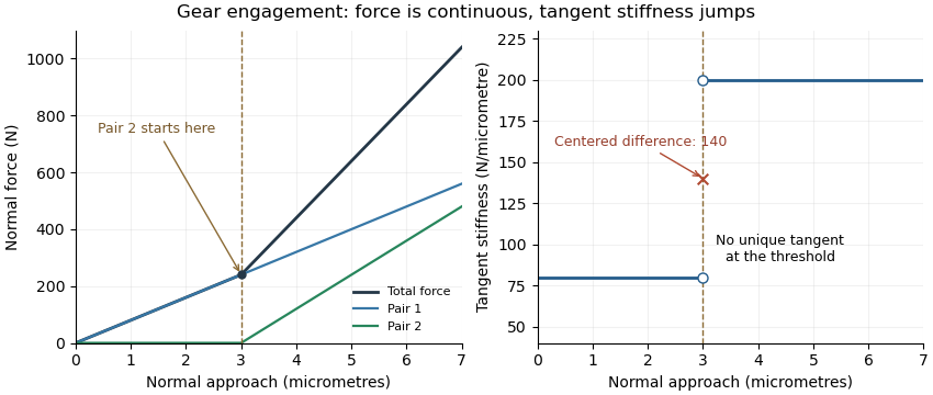
Original unilateral-contact model: continuous force, a gear tooth engagement threshold, and distinct one-sided gear mesh tangent stiffness values
. Details. 
The measured displacement channel also matters. If a contact stiffness is in series with support stiffness , their mechanical compliances add, givingA measurement spanning the whole assembly would therefore not isolate the contact stiffness.
For a perturbation experiment, report the mean load, mesh position, displacement endpoints and whether the increment crosses a contact transition. A primary NASA analysis used a coupled tooth-stiffness/dynamic-load calculation; the derivative above explains a local quasistatic limit, rather than replacing that dynamical model.[ref]
Gear sliding velocity is the relative tangential surface velocity at a tooth contact. It must distinguish the common point where the tooth surfaces touch from the two material points instantaneously occupying it. For an ideal fixed-axis external involute pair, relative normal velocity vanishes, but relative tangential velocity generally does not. It is zero at the gear pitch point and grows with distance from it along the gear line of action.[ref]
Elements of Metric Gear Technology by SDP-SI. §3.1, common base-circle tangent, line of action and pitch-circle geometry
Let be the pitch point, a contact point and a unit direction along the line of action. Use a common positive rotation axis for both signed angular velocities. The rigid-body velocity law givesSubtracting these expressions and using equal velocities at givesThe result is perpendicular to the common normal, as the contact constraint requires. External gears rotate in opposite directions, so the sliding-speed magnitude is , rather than their speed difference in magnitude.
For and , at the signed tangential sliding velocity is ; at it is . Both vanish at . Doubling both shaft speeds doubles gear sliding velocity at the same contact location, while leaving the ideal gear ratio unchanged. This connects geometry and running speed to gear sliding-friction loss. The formula concerns a two-dimensional spur gear contact; general three-dimensional contact requires the complete surface velocities and common normal.
The gear pitch point is where the gear line of action meets the line joining the gear centers. For a fixed-axis external involute pair, it is the tangency point of the operating pitch circles. The point is a geometric location in the mesh, rather than a material mark permanently attached to one tooth.[ref]
Elements of Metric Gear Technology by SDP-SI. §3.1, pressure-angle, line-of-centers and base-circle tangent geometry
Let the gear centers be separated by , with tooth counts . Their operating radii locate the pitch point atFor external signed angular velocities, . The two hypothetical material points occupying the pitch point therefore have the same instantaneous velocity. This is the local rolling without slipping property used to construct the operating pitch circles.
For an original example, use20 and40 teeth separated by . The pitch point is20mm from the first center and40mm from the second. With and , both surface velocities at that location have magnitude and the same direction. Ideal relative gear sliding velocity is zero there.
Elsewhere on the gear path of contact, the two tooth surfaces can slide even while maintaining the required normal contact condition. The pitch point remains fixed in this fixed-axis geometry, while successive tooth-contact points advance through the mesh. Whether the pitch point itself belongs to a particular usable contact interval depends on the available flanks; the geometric definition does not assert that every modified tooth profile physically contacts at that point.
The gear path of contact is the locus of actual tooth-contact points during an engagement. For a conventional external involute pair, its active part is a finite straight segment of the gear line of action. Its endpoints are set by the usable tooth flanks, rather than by the infinite geometric line alone. The part before the gear pitch point is the gear path of approach; the part after it is the gear path of recess in the stated direction of transmission.[ref]
KHK Gear Nomenclature. “Length of Path of Contact”, active line segment, approach and recess definitions
For a standard noninterfering external pair driven by gear1, let be tip radii, base radii, operating radii and the operating pressure angle. When tip circles bound the full usable contact,Adding gives . The two lengths need not be equal even when the gears use the same module and reference angle.
For the original module2,20/40-tooth example at20degree reference angle and60mm standard separation, tip radii22 and42mm give and . Their sum is ; dividing by gear base pitch gives transverse gear contact ratio about1.6352.
These are distances along the line of contact, not arc lengths traveled around a pitch circle. A shortened or altered flank can reduce the active interval, and interference can invalidate the full tip-limited construction. The labels approach and recess also depend on which direction is being followed. A practical contact inspection therefore needs the profile geometry and transmission direction, not just a sketch of two nominal pitch circles.
Gear contact duration is the time for a specified tooth pair to traverse its active gear path of contact. For a fixed-axis external spur gear pair at constant speed, the contact location advances along the gear line of action at the common gear base-roll speedThis is the speed of the contact location along a geometric line, not the relative tooth-surface gear sliding velocity. The latter vanishes at the gear pitch point, while the contact location continues moving. For active path length , duration is . The geometry relates gear contact ratio to active path length divided by gear base pitch.[ref]
The time between successive tooth-pair entries is , with gear mesh frequency . Since for compatible operating geometry, the base-circle distance advanced per entry isConsequentlyA contact ratio above1 means one pair remains engaged after the next pair enters; it does not mean one pair contacts for an entire shaft revolution.
For the standard module2,20/40-tooth example with20degree reference angle, active length is9.65457mm and base pitch is5.90426mm. At driving angular velocity , , and . The entry interval is6.28319ms, giving . Doubling both shaft speeds halves duration while preserving geometric gear contact ratio. Variable speed requires integrating the changing base-roll speed; a helical gear also needs a stated transverse slice or a whole-face contact convention.
Gear base-roll speed is the rate at which base-circle rolling advances an ideal involute contact along the gear line of action. For a fixed-axis external pair at constant speed,The equality follows from the tooth-count speed ratio and compatible base pitches. It describes the rate of change of contact position along a geometric line, rather than the gear sliding velocity between material points on the flanks. Base circles and their common tangent define this geometry.[ref]
KHK Gear Nomenclature. Basic Guide B §3, printed pp.20–21, involute/base-circle construction; “Length of Path of Contact”, active line-of-action segment
For standard module2 gears with20 and40 teeth at20degree reference angle, base radii are and . Signed angular velocities and give the same . The first gear's reference-circle tangential speed is1m/s, so base-roll and pitch-circle speeds are distinct.
In one tooth-entry interval, the base circle advances one gear base pitch:With , the example advances5.90426mm per entry. An active contact length9.65457mm therefore gives gear contact duration .
For compatible involute teeth, changing center distance changes the operating pressure angle and operating pitch circles, while leaving the manufactured base circles unchanged. At the same shaft speeds, base-roll speed is therefore unchanged even though the usable contact length may change. This separates a kinematic rate from the active interval needed to calculate contact time. If speed varies, contact displacement follows ; a constant-speed quotient is then only an approximation.
The gear path of recess is the part of the active gear path of contact followed after passing the gear pitch point, in the stated driving direction. For a standard external involute pair driven by gear1, contact ends at the driving gear's tip circle when that tip bounds the usable profile. The recess length lies on the gear line of action; it is not an arc of the gear pitch circle.[ref]
KHK Gear Nomenclature. “Length of Path of Contact”, recess segment from pitch point to final contact
Use driving-gear tip radius , base radius , operating radius and operating pressure angle . The base-circle tangent triangle givesFor a standard module2,20/40-tooth pair at60mm separation and20degree reference angle, , and yield . The corresponding gear path of approach is about5.0586mm, so the pitch point does not bisect the active contact interval.
At driving angular velocity , the contact-location speed is . Recess therefore lasts about4.891ms. Adding approach gives gear contact duration . Tooth-passage frequency is , so , agreeing with the transverse gear contact ratio calculated as active length divided by gear base pitch.
A shorter usable driving flank reduces recess and can change gear sliding-friction loss, because sliding grows with distance from the pitch point. The tip-circle formula alone cannot describe profile modifications or an interfering contact. The geometry and direction must be specified before applying the approach/recess labels.
The gear path of approach is the part of the active gear path of contact followed before the contact reaches the gear pitch point. For a conventional external involute pair in the stated driving direction, contact starts where the driven gear's tip circle intersects the usable gear line of action, and then moves toward the pitch point. This is a straight-line distance along the common normal, not an arc around a pitch circle.[ref]
KHK Gear Nomenclature. “Length of Path of Contact”, approach segment from first contact to the pitch point
Let gear1 drive gear2. Write for gear2's tip radius, for its base radius, for its operating radius and for operating pressure angle. A right triangle from the base-circle tangency gives tip-to-tangency distance . Subtracting the pitch-point-to-tangency distance givesThis formula assumes the full tip-limited interval is usable without interference or profile truncation.
For an original standard module2,20/40-tooth pair at60mm center distance and20degree reference angle, gear2 has tip radius42mm, operating radius40mm and base radius . Consequently . If gear1 rotates at , contact advances along the line at , giving an approach contribution to gear contact duration of about . This contact-location speed differs from gear sliding velocity, which tends to zero on arriving at the pitch point.
The total active length adds gear path of recess. Reversing the followed engagement direction exchanges which segment is called approach and which is recess. If altered usable flanks exclude the nominal pitch point, an assumed positive tip-limited formula must not replace an inspection of the actual active interval.
Articles by others on the same topic
There are currently no matching articles.