Use the ideal electrically short Hertzian dipole, , with negligible ohmic loss. Far-field statements additionally require an observation distance large compared with the wavelength and source dimensions. These assumptions distinguish its radiation from near-field coupling and from scattering by a general extended antenna structure.
Choose along . If the end charges are separated by fixed distance , then . The conventional current into the positive end is , soThe current is in phase quadrature with the dipole moment. A different time origin or current orientation changes the sine's sign or phase but not its amplitude. Units check: .
For a dipole along , axial symmetry removes dependence on azimuth . In the Lorenz gauge, its magnetic vector potential points along , so it has spherical components , and . The scalar potential is also independent of . Thus , while taking leaves only an azimuthal magnetic field:The generally nonzero components are . This statement includes the full dipole near field. In the leading radiation zone term, also vanishes; its nonzero full-field contributions fall faster than . Confusing those two levels of approximation would incorrectly suggest four exact zeros everywhere.
For a localized current density, the retarded magnetic vector potential isAt large , replace the amplitude denominator by . For an electrically short dipole, the delay difference across its length is negligible compared with an oscillation period, so evaluate all currents at . The continuity equation for electric charge gives the identitywhere localization makes the boundary term vanish. HenceIn this gauge its Cartesian direction is fixed and its magnitude depends only on and the retarded dipole motion, with spreading. Spherical components have the geometric factors and above; the angular radiation pattern arises after differentiating the potentials, not from an isotropic radiated intensity.
The outgoing radiation field has magnitude and . The radial Poynting vector, averaged over one cycle, givesThus the cut has a two-lobed shape, with zeros along and maxima along . In the plane, throughout and the cut is a circle: there is no azimuthal dependence. At fixed direction the flux falls as , while power per solid angle is independent of observation radius.
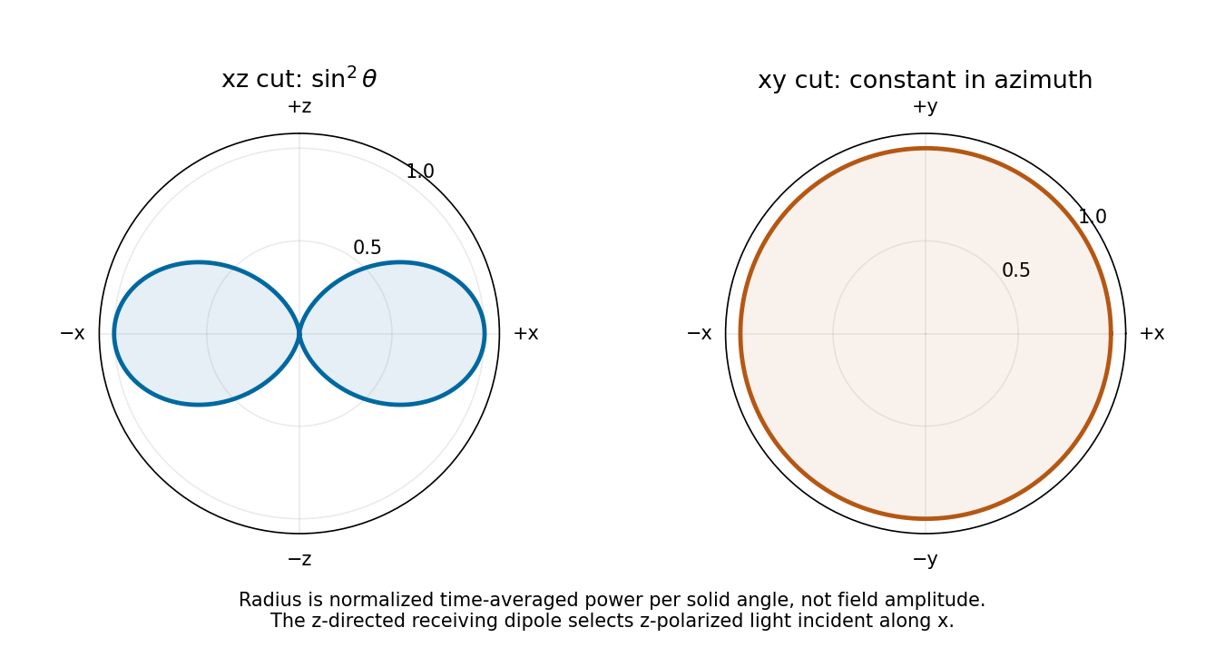

As a receiver for propagation along , the antenna responds to the incident electric field component along . For linear polarization at angle to , the available load power is proportional to : it is maximal for polarization and zero for polarization. Equal incident intensity in circular polarization gives half the matched-linear power. This polarization response follows from the induced voltage's projection along the dipole axis.
Antenna gain in direction compares the far-field power per solid angle with an isotropic radiator using the same accepted input power:It includes radiation efficiency; for the lossless dipole . The antenna effective area is defined for incidence from a specified direction with matched polarization and conjugate impedance matching:Its units are square metres and it need not equal the physical metal area.
For ordinary reciprocal antennas, electromagnetic reciprocity makes the coupling between two matched ports the same when transmitter and receiver are exchanged. Free-space transfer in one direction is proportional to , while the reverse transfer is proportional to . Thus must be a universal factor at that wavelength, independent of antenna or direction. The supplied relation fixes it asEquivalently, thermal detailed balance prevents an angular receiving pattern from collecting more radiation than its reciprocal emitting pattern would return in equilibrium. Reciprocity and the specified matching are the assumptions behind this statement; it is not a general theorem for active nonreciprocal devices.
Integrating the radiation pattern uses , so its lossless gain isThe receiver lies on the axis, broadside to both -directed dipoles. Thus and their linear polarizations match. At , , givingAt separation , the incident flux is . The Friis transmission equation therefore gives the matched-load powerThe far-field and weak-coupling approximations are well satisfied at a distance of about wavelengths for an electrically short dipole. Matching refers to the available received power, not interception of all power in a geometric area equal to the wire's physical size.
The receiving dipole remains matched. To model its actual reradiation, let its feed impedance be with no ohmic loss, and its matched load be . The induced current dissipates equal powers in the load and in radiation resistance. Thus matched-load scattering of a Hertzian dipole has , even though its port is matched.
The scattered wave has the same dipole gain toward the original antenna. Applying the reciprocal link factor a second time gives the reciprocal Hertzian-dipole echo:Each leg supplies an inverse-square spreading factor. This is the carrier-averaged power during a returned pulse with the stated transmitted power during its pulse. The pulse-train average additionally depends on duty cycle, which is not given. Treating the pulses as narrowband keeps the same gain and wavelength approximation.
A matched feed does not make a physical dipole a perfect absorber with zero external scattering. A model retaining only an antenna load-mismatch echo would set its reflected travelling-port wave to zero and would not determine this reradiation. Conversely, an arbitrary antenna structure can add scattering not fixed by gain and effective area alone. The numerical answer uses the ideal lossless Hertzian-dipole scattering model just stated.
Articles by others on the same topic
There are currently no matching articles.