Use an ideal operational amplifier with its non-inverting terminal grounded, an input resistor and a feedback capacitor , as in the upper circuit. Stable unsaturated negative feedback holds the inverting terminal at virtual ground, while the input current into the amplifier itself vanishes.
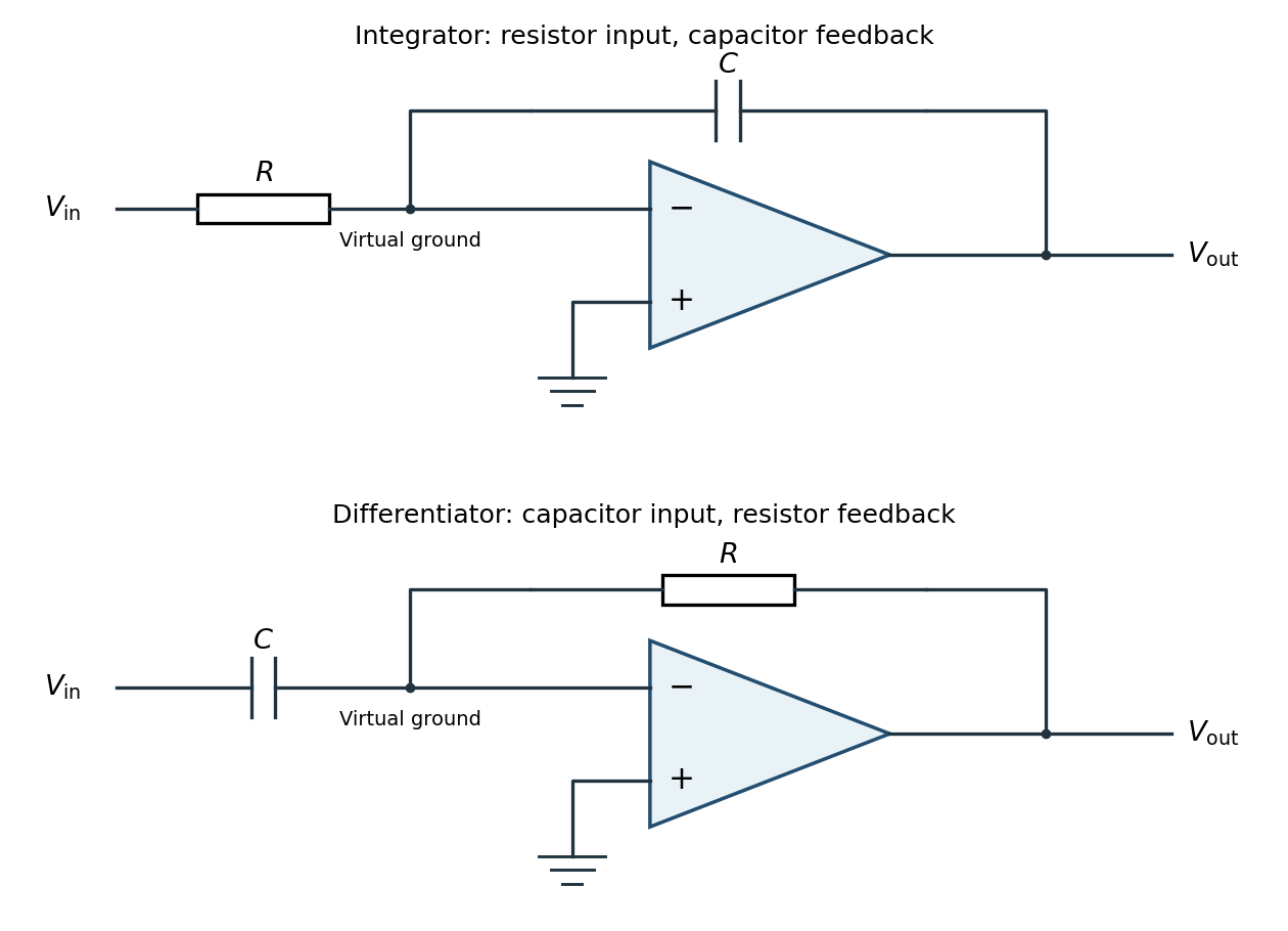
Inverting operational-amplifier integrator and differentiator circuits
. Details. 
Applying Kirchhoff's current law at the inverting node givesThus the circuit is an inverting op amp integrator, with its integration constant set by the initial capacitor charge. A constant input makes the output ramp until a real amplifier reaches a supply rail. A practical low-frequency design usually adds a large feedback resistor to limit drift; the ideal integral relation applies where the feedback capacitor dominates.
Interchange the input and feedback components: put the capacitor between the input and the inverting terminal, and the resistor between the output and the inverting terminal. Keep the non-inverting terminal grounded, as in the lower circuit above. For an ideal operational amplifier under unsaturated negative feedback, the inverting node remains at virtual ground.
The input capacitor current is . It flows through the feedback resistor, givingThis is an inverting op amp differentiator. Its ideal gain magnitude increases with frequency, so it strongly amplifies high-frequency noise. Practical differentiators include components that restrict the useful band and stabilize feedback; that qualification does not change the displayed ideal low-amplitude relation within the operating band.
Articles by others on the same topic
There are currently no matching articles.