Source paper: Oxford source archive, member
Prelims papers/CP2_June_2016.pdf. The cover dates this ordinary paper to 7 June 2016. Unlettered marked blocks are indexed a, b and so on; all four Section B options are treated.Take the electrostatic potential energy to vanish for infinitely separated point charges, and write . The first charge costs no work to place. Bringing the second to distance costs ; the third is distance from both existing charges and costs . Thus the external quasistatic assembly work isEquivalently, sum over the three distinct pairs in the equilateral triangle. Counting both ordered pairs without a compensating factor of one half would double the answer. The positive result applies to either sign of , since all three electric charges have the same sign.
By symmetry, the resultant Coulomb force on each charge points along the line from the centroid to its vertex. Their accelerations and subsequent speeds are equal, so the centroid remains fixed and the equilateral triangle expands without rotating. Each charge follows a straight radial trajectory; the separation grows and the repulsive force decreases.
For example, if the instantaneous side is and the centroid-to-charge distance is , the two pair forces have a angle between them. Their resultant is , along the outward radius. This confirms that the symmetric shape persists.
Assuming release from rest, nonrelativistic motion and negligible radiation losses, energy conservation givesThe three velocity vectors sum to zero, consistent with momentum conservation. Their magnitudes approach the displayed value as the remaining electrostatic potential energy tends to zero.
The Lorentz force isFor , the magnetic part is perpendicular to the velocity, so its instantaneous power vanishes. The speed and kinetic energy therefore remain constant. Decompose the initial velocity into along the uniform magnetic field and perpendicular to it. The parallel component is unchanged, while the perpendicular component rotates uniformly.
For a nonrelativistic particle with , the resulting helical motion hasHere is the Larmor radius, the cyclotron frequency in angular units, and the axial advance per turn. Opposite signs of electric charge give opposite senses of rotation. Pure perpendicular motion gives a circle; pure parallel motion gives a straight line. If or , there is no magnetic deflection. At relativistic speeds, replace in the radius and period by ; stays constant because the magnetic force does no work.
Translational and reflection symmetry parallel to the slabs imply . The differential Gauss's law is . Starting at the left boundary with givesThere is no singular surface charge at , so the normal electric field is continuous there: . Integrating through the positive slab givesThe second expression indeed returns to zero at , because the two total charges per unit area are and . For , the electric field throughout the interior points from the positive slab towards the negative slab, along ; reversing reverses the directions. The piecewise linear profile is a useful consequence of the uniform volume charge density.
Define the requested electric potential difference as . Since ,soGeometrically, the integral is the area of two triangles under the signed electric field profile. For , the right-hand plane is at higher electric potential. Choosing , a continuous interior electric potential is in the first slab and in the second. These expressions also verify the boundary values directly.
Let and choose the rotating area normal to coincide initially with . At time its angle to the applied magnetic field is , so the external magnetic flux is . Faraday's law therefore givesIn the high-electrical resistance approximation, neglecting the loop's self-inductance, Ohm's law givesThe displayed signs specify positive circulation by the chosen normal; reversing the reference circulation reverses both signs. The high-electrical resistance assumption is quantitatively if the loop has self-inductance . Otherwise the current lags the induced electromotive force and must be obtained from .
The magnetic dipole moment is and its magnetic torque is . Its component along the rotation axis opposes the imposed rotation. For positive , the external driving torque needed to keep the angular velocity constant isAveraging over a complete rotation, with , givesAs an independent sign and dimension check, . Thus the mechanical input power equals the mean Joule heating; a passive loop cannot supply a sustained driving torque. This average assumes the same negligible-self-inductance approximation as the current expression.
The magnetostatic Ampère's law, in vacuum, isThe path direction and surface normal are related by the right-hand rule. Taking the divergence of the differential law gives , since the divergence of a curl vanishes. However, charge conservation requires the continuity equation , which need not vanish during charging.
Using Gauss's law, , the combination has zero divergence. Replacing by this conserved total current density gives the Ampère-Maxwell equation:Its integral form is . The extra term is the displacement current. In a charging parallel-plate capacitor, a surface cutting the wire encloses a conduction current , while a surface through the vacuum gap encloses no conduction current but has . This modification makes the magnetic circulation independent of which spanning surface is chosen. The vacuum displacement current represents a changing electric field, not literal transport of charge across the gap.
Under the Rayleigh criterion, two equally bright, mutually incoherent point sources are just resolved when the central maximum of one diffraction pattern lies at the first minimum of the other. Their intensities, rather than their electric-field amplitudes, add. For an ideal circular aperture of diameter , the first dark ring of the Airy disk givesThe angle is in radians in the small-angle limit. This is a conventional resolution criterion for a specified aperture and wavelength; it is not an absolute prohibition on estimating a source separation by fitting noisy data under additional assumptions.
With , the circular-aperture diffraction limit is when is in metres. No wavelength is specified, so a unique numerical diffraction angle cannot be deduced. Taking representative visible light at givesFor a roughly square receptor arrangement with surface density , the characteristic receptor pitch is . With the retina behind the lens, that pitch subtendsThis is an order-of-magnitude estimate of the point-separation scale from retinal sampling. A periodic intensity pattern needs at least two samples per period under the Nyquist–Shannon sampling theorem, giving a corresponding period angle of about or . A different receptor packing changes the pitch by an order-one geometric factor; density alone does not specify a full sampling lattice or a contrast threshold.
At a pupil and the chosen visible wavelength, the optical diffraction limit is somewhat finer than the receptor pitch. The supplied model is therefore not purely diffraction limited: retinal sampling is comparable to, and slightly more restrictive than, ideal aperture diffraction. Real optical aberrations and neural processing can further reduce resolution. Different wavelengths or a smaller pupil can change which effect dominates.
Use an ideal operational amplifier with its non-inverting terminal grounded, an input resistor and a feedback capacitor , as in the upper circuit. Stable unsaturated negative feedback holds the inverting terminal at virtual ground, while the input current into the amplifier itself vanishes.
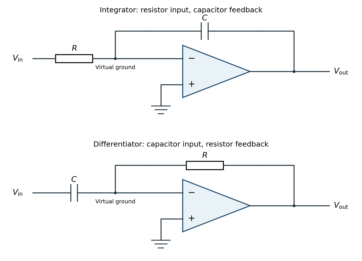
Inverting operational-amplifier integrator and differentiator circuits
. Details. Applying Kirchhoff's current law at the inverting node givesThus the circuit is an inverting op amp integrator, with its integration constant set by the initial capacitor charge. A constant input makes the output ramp until a real amplifier reaches a supply rail. A practical low-frequency design usually adds a large feedback resistor to limit drift; the ideal integral relation applies where the feedback capacitor dominates.
Interchange the input and feedback components: put the capacitor between the input and the inverting terminal, and the resistor between the output and the inverting terminal. Keep the non-inverting terminal grounded, as in the lower circuit above. For an ideal operational amplifier under unsaturated negative feedback, the inverting node remains at virtual ground.
The input capacitor current is . It flows through the feedback resistor, givingThis is an inverting op amp differentiator. Its ideal gain magnitude increases with frequency, so it strongly amplifies high-frequency noise. Practical differentiators include components that restrict the useful band and stabilize feedback; that qualification does not change the displayed ideal low-amplitude relation within the operating band.
The method of images replaces a conducting boundary by fictitious point charges placed outside the physical region being solved. Choose their positions and strengths so that the resulting electric potential has the required constant value on each conductor. The uniqueness theorem for the electrostatic potential then guarantees that this solution equals the physical solution in the allowed region, provided the other boundary conditions are also satisfied.
For a plane held at zero electric potential, a real charge a height above the plane has an image the same distance below it. The pair's electric potential vanishes everywhere on the plane. Its tangential electric field consequently vanishes there, as required in electrostatic equilibrium. The image is a mathematical representation of the induced surface charge, not a physical charge placed inside the conductor. Forces on the real charge can be computed from the image field, but total physical electrostatic energy must account for the conductor's induced response rather than simply counting a full real-plus-image pair energy.
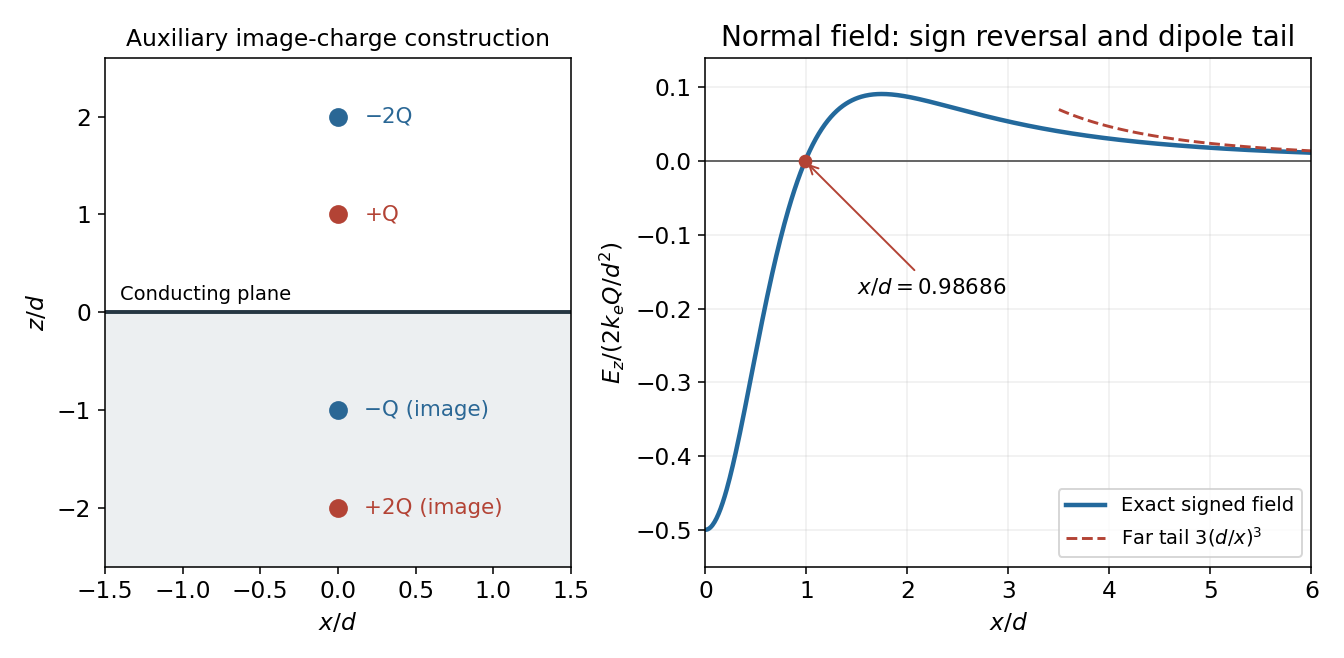
Use the standard infinite-plane boundary condition: the sheet is an equipotential, with no imposed uniform background electric field and the electric potential tending to zero far from the localized charges. The images of at and at are at and at .
At the point directly below the real charges, horizontal components vanish. The first real-image pair contributes along , while the second contributes . ThereforeFor , the electric field points downwards into the sheet. The expression is the one-sided vacuum limit; the electric field inside the conducting material is zero. A prescribed uniform background field would be an additional boundary condition and would change this result.
Let denote the radial distance from the axis in the plane, and write . A charge at height and its image give a combined normal electric field at ; the tangential components cancel. Superposing the two pairs yieldsThe conductor boundary condition gives , soTo integrate the induced surface charge, use concentric annuli of area . Since ,The local surface charge density is negative near the origin but positive farther out; integrating only the negative patch would miss the total. The total real charge is , so the induced also agrees with the sum of the two image charges. An isolated finite plate constrained to zero net charge would require a different global boundary-value problem; the formula is the infinite-plane solution just specified.
Set the normal electric field to zero and cancel its nonzero overall factor:Taking the power gives , henceThe numerical value is independent of the nonzero magnitude of . Beyond this radius the signed normal electric field is positive. Thus its magnitude first falls to zero, rises again and eventually decays; it is not globally monotone.
For , expanding each denominator givesThis is a dipole rather than a monopole tail. The real-plus-image charge distribution has zero total charge and dipole moment ; in its equatorial plane a dipole produces , confirming the coefficient and sign.
Spherical symmetry and the vacuum Gauss's law imply in the gap, where is constant. Integrating the electric field between the two equipotentials givesConsequentlyThe inner charge is , which reproduces the spherical capacitor capacitance . The radial direction is outward for positive and inward for negative ; the formula represents the signed field, not just its magnitude.
The electric field magnitude falls as throughout the vacuum gap, so its maximum occurs just outside the inner sphere:ThusInside the metal the electric field is zero. The one-sided gap value is the relevant value for dielectric breakdown; the ideal zero-thickness conducting boundary itself should not be assigned a single field value across its surface-charge discontinuity.
Inserting an independently biased conducting sphere makes two vacuum gaps, each with its own constant radial electric flux. Let and be the coefficients of . The two potential drops areThereforeThe middle conductor can carry net electric charge, so and need not be equal. Its charge is , consistent with the jump in the normal electric field. For both fields point outwards; outside that interval one of the gap fields reverses direction.
The largest field in each gap lies at that gap's smaller radius. Thus the quantity to minimize isFor positive , projecting any outside back to that interval reduces both absolute potential drops, so the optimum lies inside it. Within the interval, one candidate maximum decreases linearly with and the other increases linearly. Their maximum is minimized at their intersection, not by making the potential drops equal.
With , , and , the two maxima are and in . Equating them givesThe maximum is halved relative to the two-sphere system and is attained at both and . At and the optimized field is only about ; at the charged middle shell produces a jump.
For plotting, the two-sphere electric potential is . In the three-sphere system it isThe electric potential remains continuous at , while its radial derivative changes there. The graphs show both the continuous potentials and the one-sided gap fields; the marked endpoints identify all maxima.
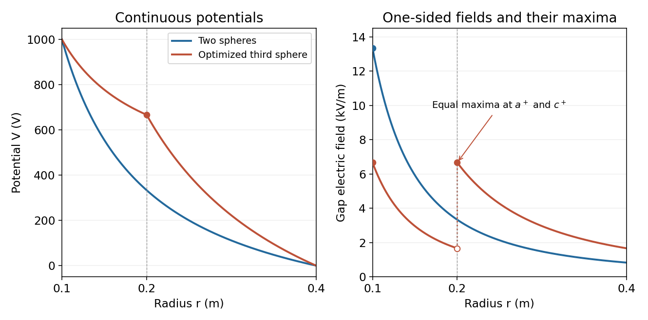
Potential and electric field before and after optimized intermediate-sphere bias
. Details. Adopt positive object and real-image distances and measured from a converging thin lens, with the object on the left. A ray through the lens centre is undeviated in the thin-lens approximation. For object height and signed image height , similar triangles give .
A second ray leaves the object parallel to the axis, reaches the lens at height and then passes through the far focal point. Its height at distance is . Equating the two descriptions givesThe signed transverse magnification is . Since a real image has for , : it is inverted. Its size relative to the object is .
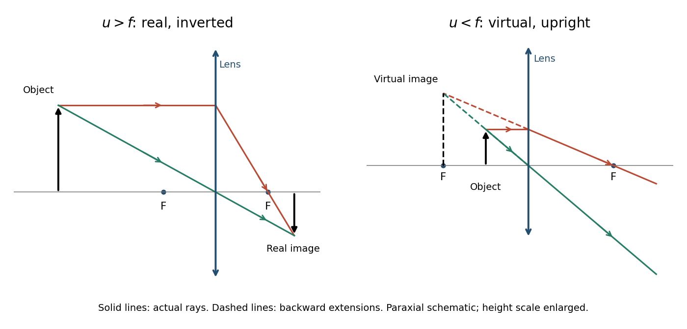
The derivation assumes the paraxial approximation, a negligible lens thickness and a focal length defined in the surrounding medium. The ray diagrams show actual paths as solid lines and backward extrapolations as dashed lines.
For a real image, and . The object-to-image separation isIts excess above factors into a nonnegative expression:ThereforeAt this minimum the image is inverted and has unit absolute magnification. The restriction to a real object and a real image matters: the positive separation used here is not the same quantity as a signed distance to a virtual image.
A real image is a point where the actual outgoing rays converge; a screen placed there can intercept the focused light. A virtual image is a point from which the outgoing rays appear to diverge: only their backward extensions intersect, so a screen at that apparent point does not receive a focused real image from the same rays.
For a converging thin lens with and a real object a distance away, the lens relation gives . If , then : the image is real, on the opposite side, and inverted. If , then : the image is virtual, on the same side as the object, upright and enlarged, with .
At , the emergent rays are parallel and the image is at infinity; there is no finite focused image. For an object very far away, from above. These are conditions for a real object in the stated lens convention, rather than claims about all systems with virtual incident objects.
For a lens between an object and a screen, and the thin lens relation requires . Eliminating gives the quadratic equationFor , both roots lie between and , and they exchange the object and image distances. Both therefore focus the image on the same screen, with reciprocal absolute magnifications. The distance between lens positions isThe existence qualification is essential: for the two roots coincide and there is only one distinct position; for there is none. For example, makes the discriminant negative, providing a concrete counterexample to an unconditional assertion of two positions. This is the basis of the Bessel lens displacement method, with when two distinct positions can be measured.
Choose the phasor convention and similarly for the electric current. In a linear sinusoidal steady state, differentiation becomes multiplication by , and complex impedance is . Kirchhoff's current law and Kirchhoff's voltage law then become algebraic equations that retain both amplitude and phase information.
For a resistor, , so . For a capacitor, , while an inductor obeys . ThereforeThe resistor's electric potential difference and current are in phase. The inductor's electric potential difference leads its current by ; the capacitor's current leads its electric potential difference by . Replacing by conjugates every impedance but leaves these physical lead-and-lag statements unchanged. The phasor method describes the steady state; switch-on transients must be added separately when initial conditions are relevant.
A series connection has the same electric current through each element, so complex impedances add:For , define . ThenAbove resonance, the circuit is inductive and electric potential difference leads current; below resonance it is capacitive and electric potential difference lags current. Atthe inductive and capacitive reactances cancel and is purely resistive. The same resonance condition holds for an ideal series circuit independent of the drive amplitude.
A parallel connection has the same electric potential difference across each element, so the electrical admittances add. With and ,For a prescribed sinusoidal current, . Thus the voltage-minus-current phase isBelow the circuit is inductive, so electric potential difference leads current; above it the circuit is capacitive, so electric potential difference lags current. At , the reactive branch currents cancel, and . This is the impedance maximum for positive finite , whereas the series circuit has its impedance minimum at the same frequency. It does not mean that either individual reactive branch current vanishes.
The source's variable inductor and variable resistor are in parallel. Let their combined complex impedance beUse the left and right source terminals as the drive nodes. The upper divider has arms and ; the lower divider has arms and . At bridge balance, the detector draws no electric current and the divider midpoint electric potential differences agree, soSubstitution and cancellation at a nonzero drive frequency giveEquating real and imaginary parts yieldsThe first expression has units of resistance and the second units of inductance. Both are independent of the drive amplitude and, for ideal frequency-independent components, of the chosen nonzero drive frequency. At zero frequency the ideal inductors short their arms and the cancellation would not be valid as a measurement of .
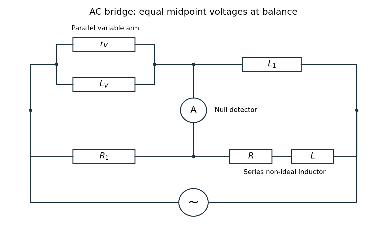


Two applications are precision comparison of an unknown electrical resistance with calibrated standards in a Wheatstone bridge, and detecting small resistance changes in a strain gauge or resistance thermometer. Alternating-current bridges additionally compare capacitance, inductance and dielectric losses; this particular bridge determines the two parameters of a non-ideal inductor from a null measurement.
Articles by others on the same topic
There are currently no matching articles.