A mercury-vapor lamp is an extended, spontaneously emitting source, so practical interference requires spatial filtering and spectral selection. A narrow illuminated source slit gives sufficient spatial coherence; selecting one strong spectral line improves temporal coherence and avoids overlapping differently spaced interference fringes.
In the classical double-slit experiment, both apertures are illuminated by the same narrow source. The arrangement is symmetric, permits direct measurement and adjustment of slit separation, and has equal optical materials in the two paths. Its main drawbacks are low transmitted intensity through narrow apertures, the need for a well-made closely spaced slit pair and alignment, and the finite single-slit diffraction envelope. A broad source washes out interference fringes.
Lloyd's mirror uses the direct wave from a narrow source and the reflected wave, which appears to come from its virtual image behind a plane mirror. It requires only one physical source slit; the mirror can be adjusted to make a small effective source separation without manufacturing a double aperture. Only the direct-reflected overlap region shows interference fringes. Finite mirror size, alignment, surface quality, unequal intensities and the polarization-dependent reflection coefficient can reduce visibility. For the usual grazing reflection from glass, the reflected electric wave acquires approximately a phase shift, so the zero path-difference position is dark rather than the bright central fringe of the symmetric classical double-slit experiment. Both arrangements still require adequate spatial coherence and temporal coherence.
Illuminate a narrow entrance slit with the mercury-vapor lamp, use a collimating lens to illuminate two parallel narrow slits coherently, and insert a bandpass filter selecting the green line. Place a screen or scanning detector a measured distance beyond the double slit. The source slit and the two apertures should be parallel. The aperture widths should be appreciably smaller than their separation to provide an extended diffraction envelope; the green filter should reject the other strong mercury lines. The layout is drawn below.
For slit separation and observation angle , the optical path difference in air is . At a bright interference fringe, . For a distant screen and small angles, , givingMeasuring several interference fringe spacings and dividing by their number reduces relative position error. The derivation assumes the slits have equal phase on illumination and that the screen region lies within their common diffraction envelope.
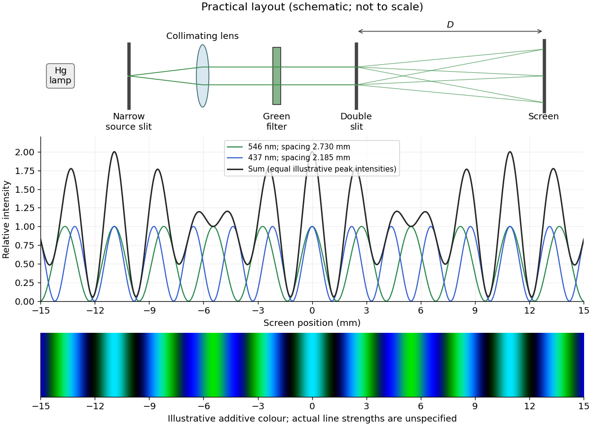

The two wavelengths have independent interference patterns. Their interference fringe spacings areDifferent optical frequencies do not maintain a fixed mutual phase over the detector's integration time, so their intensities add. For narrow equal slits, suppressing the slowly varying diffraction envelopes, one may writeThe relative line strengths are not supplied; the figure illustrates equal peak intensities rather than inferring a quantitative brightness ratio. At both colours are bright, producing a blue-green mixture. Away from the centre the green and blue interference fringes progressively separate, creating alternating colour and brightness variations; places where one line is dark can still be bright in the other. Neither two-line mixing nor its central maximum is generally white.
Across , the green maxima occur at for , and the blue maxima at for . Near , the fourth green and fifth blue maxima nearly coincide: and . The mismatch shows that these are near coincidences, not exact ones for the given wavelengths. The plotted central interval includes all these maxima.
Articles by others on the same topic
There are currently no matching articles.