Temporal optical coherence compares a field at one position with a delayed copy. In a Michelson interferometer, unequal round-trip lengths supply this delay. Even a source with rapidly changing wave phase can give high interferometric visibility close to zero delay, because both arms then deliver nearly the same source history. A source narrowed in optical spectrum generally retains correlation over larger delays; a single width does not describe sources with several separated lines. [ref]
https://ocw.mit.edu/courses/2-71-optics-spring-2009/bebe78c6a2ae2603a0d1a3ea85e0b4ca_MIT2_71S09_lec22.pdf. MIT 2.71/2.710, lecture 22, slides 2–5: temporal and spatial coherence
.For a stationary scalar field, choose the carrier convention , with frequency in cycles per second. Let be its spectral density per unit frequency, with . Its normalized field correlation is the Fourier transformThe optical spectrum weights the rotating contributions; a broad spread of frequencies allows them to cancel at short delays. This is the stationary field correlation–spectrum relation. The relevant spectrum is that of the optical field in the detected mode, rather than the low-frequency fluctuations of a detector's light intensity. [ref]
https://www.rp-photonics.com/optical_spectrum.html. Rüdiger Paschotta, RP Photonics Encyclopedia, Optical Spectrum: optical field spectrum and temporal coherence
.Here are two stipulated line profiles, each centered at with full width at half maximum . Write and use normalized profiles on the whole detuning line:The first is a Lorentzian, mathematically a Cauchy distribution; the second is a Gaussian function. Taking their Fourier transforms gives, with the carrier factor omitted from the magnitudes,These are calculated model results, not measured line profiles. The detuning approximation treats the narrow line as extending to arbitrarily large positive and negative ; for optical applications require . Exact spectra of the complex positive-frequency field have no negative absolute frequencies. Changing to angular frequency replaces by ; it must not silently preserve the same numerical constant.
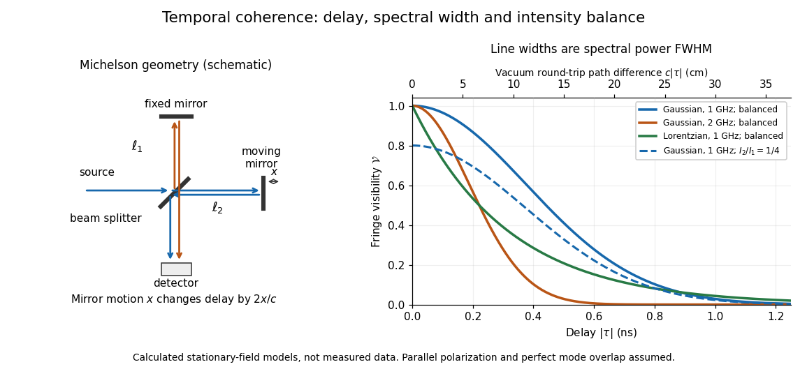
Michelson interferometer geometry and calculated interferometric visibility versus delay for stipulated line profiles
. Details. 
Equal detected single-arm light intensities give interferometric visibility equal to the correlation magnitude. Doubling the Gaussian full width at half maximum from to halves every fixed-contrast delay. At the model gives Gaussian interferometric visibility approximately at and at ; the Lorentzian gives . The dashed curve instead keeps the Gaussian correlation and changes to , multiplying all interferometric visibilities by . Its lower contrast at zero delay therefore comes entirely from intensity imbalance.
Two narrow incoherent lines of powers and wave-number difference give visibility in a Michelson scan of one-way arm difference . The minimum is , and revivals repeat in . Finite linewidth damps this envelope.
Two delayed copies of the same laser field probe its first-order optical coherence. With equal detected intensities and matched polarizations, the interferometric visibility is . A Lorentzian line shape of frequency full width at half maximum gives . For a fibre length difference , the delay is , where is the group index. Hence . Replacing by the effective phase index requires negligible dispersion. Polarization mismatch, unequal intensities and uncontrolled phase drift can reduce visibility independently of linewidth.
Two equally intense monochromatic spectral components have normalized first-order optical coherenceThe visibility zeros occur at , while its revivals repeat every . This envelope describes self-interference of each spectral component after a delay, not a time-resolved measurement of inter-frequency beating at one fixed point. Unequal line intensities prevent complete cancellation at the minima.
For two equal-intensity mutually incoherent narrow spectral lines with wavenumbers , a Michelson interferometer with optical path difference has normalized intensity , where and . With mirror displacement , the fast period is ; successive interference visibility revivals are separated by . The first visibility zero is halfway to the first revival. A signed envelope has twice the period of its absolute value. Unequal line strengths prevent perfect zeros.
Split one stationary scalar optical field into equal copies travelling at right angles with common transverse linear polarization. For wavevectors , the relative geometric delay is in vacuum, while the delay on the bisector is zero. The electric-field intensity convention gives the displayed pattern and . The mean Poynting vector points along , with magnitude in that convention. A transverse detector can record the profile if it resolves the period ; a longitudinal profile is not a transverse camera image.
For the right-angle geometry of temporal coherence from crossed beams, a physical arm-path delay gives , with the sign set by the delayed arm. A quarter-cycle optical phase delay requires ; it shifts the fringe pattern by a quarter of its period, . A path delay equal to that latter length is a different operation. Replacing the shifted correlation by a phase multiplier additionally requires the delay to be small compared with the envelope optical coherence time.
An optical coherence time summarizes the delay scale of temporal optical coherence, but requires a convention. Two useful choices are the first positive delay where , for a monotonically decaying envelope, and the integral definitionThe latter counts correlation over both signs of delay and may diverge for ideal discrete lines. [ref]
https://www.rp-photonics.com/coherence_time.html. Paschotta, Coherence Time: exponential time constant and integral definition
.For the stipulated Lorentzian and Gaussian profiles in temporal optical coherence, direct substitution and a Gaussian integral giveThe respective dimensionless coefficients are for both Lorentzian conventions, and and for the Gaussian conventions. The familiar scale is consequently an estimate, not a convention-independent equality. A source with narrow discrete lines can have repeated revivals instead of one monotonically decaying envelope, so recording the full can be more informative than one optical coherence time.
In this temporal sense, the optical coherence length is , where is the vacuum speed of light and is an explicitly chosen optical coherence time. It measures a delay as a vacuum-equivalent path difference; it does not measure transverse spatial optical coherence. [ref].
For the stipulated profiles, the convention gives for the Lorentzian and for the Gaussian. In a vacuum Michelson interferometer, changing one mirror position by changes the round-trip delay by , so the mirror travel to either of these delays is . In a medium, convert physical travel using the actual group delay, which can depend on frequency. For a narrow line centered at vacuum wavelength , differentiating gives ; this small-width approximation must use consistently defined spectral widths.
For vacuum wavelength endpoints , the corresponding frequency span is . The reciprocal-bandwidth estimate of optical coherence time is , giving . This endpoint conversion is valid even for a broad band, whereas requires a relatively narrow optical spectrum.
For constant spectral density per unit frequency in the band, the normalized first-order optical coherence is . Its first zero occurs at . A different spectral shape or a different contrast criterion changes the numerical optical coherence length; endpoints alone do not define an exact universal value.
A Michelson interferometer divides light at a beam splitter, reflects the two arms at mirrors and recombines the returning fields. For vacuum arm lengths , the delay magnitude is . At each coarse delay, a small mirror scan produces maxima and minima of the detected light intensity. A photodiode and its electrical readout resolve these changes; the scan should cover several carrier cycles while changing negligibly. MIT's laboratory guide uses a mirror actuator, photodiode and electrical drive to scan interference fringes and extract interferometric visibility.[ref]
Optical Interferometry. §§II–IV: apparatus and visibility measurement
A verified motivating experiment is Shaoul Ezekiel's MIT demonstration of source-spectrum control. A polarizer selects one or several lines from a laser whose adjacent lines have orthogonal linear polarizations. A sampled beam goes to a scanning Fabry–Pérot interferometer to check the optical spectrum; the main beam enters a Michelson interferometer, and a lens projects its interference fringes onto a screen. With one selected line the fringes retain good contrast through the demonstrated delay range. With several lines their contrast falls and returns as the arm length changes. At a fixed delay with poor contrast, selecting one line restores it; at matched arms both selections give good contrast. This control isolates the role of spectral composition rather than simply the arm position. The presentation is a qualitative demonstration, not a calibrated linewidth measurement. [ref]
https://ocw.mit.edu/courses/res-6-006-video-demonstrations-in-lasers-and-optics-spring-2008/203f69980203861f374be32d61f9940e_LixwAXsN8vg.pdf. Shaoul Ezekiel, MIT, Coherence length and source spectrum, demonstration transcript
.A deliberately simpler two-line model explains the return of contrast. Take two stationary, mutually uncorrelated monochromatic contributions of equal power at . Their normalized wave-field correlation isfor equal detected single-arm light intensities. At the two contributions' interference fringes cancel on averaging; at they agree again. This is a deduction from the stipulated spectrum, not a fit to Ezekiel's two- or three-line source. Finite individual linewidths eventually damp these revivals.
For a quantitative version of the experiment, the visibility law suggests explicit controls. Measure each arm separately at every coarse delay, subtract the detector's dark signal and any measured background, then normalize by . Keep the returning beams aligned on the same detector region with parallel linear polarizations; keep detector gain fixed and avoid saturation. Resolve the small mirror scan electrically, rather than averaging over its moving interference fringes. Repeat scans to identify vibration or drift. These controls follow from the averaging and mode-matching assumptions in first-order optical coherence; loss of contrast alone cannot distinguish source decorrelation from apparatus motion, misalignment or insufficient spatial resolution. The finite travel range gives access only to a finite range of delays.
The practical gain is that wave interference measures field correlations even when the detector cannot follow the optical oscillation itself. A long optical coherence length allows unequal-arm measurements; a short one localizes high contrast near matched delays. The beautiful feature is that both fading and reappearance of interference fringes are sums of the same rotating complex amplitudes.
Moving one mirror by changes the round-trip optical path by . Starting at a common bright centre for two commensurate wavelengths, the next common bright centre occurs when for the smallest positive integers. This is a common-multiple condition on optical path, not on the mirror displacement itself. Incommensurate exact wavelengths have no finite exact recurrence in the ideal model.
Changing both arms of a balanced Michelson interferometer by the same length changes the common phase of both returning fields. Their relative phase and detector intensity remain unchanged at every frequency. Thus balanced interference cannot select a minimum positive common arm length.
A one-way arm-length difference gives optical path difference and phase difference . An ideal constructive output port has intensity . The other output is complementary.
A Michelson interferometer turns displacement into a count of interference fringes: a moving mirror changes both the outward and return paths. This lets a wavelength act as a ruler whose divisions need no engraving. Assume normal incidence, a fixed reference arm, stable refractive index along the moving arm, and fixed vacuum wavelength . Write for the wavelength in that medium and take positive away from the beam splitter. The change in optical path difference, the accumulated phase difference, and the signed number of complete interference fringe cycles areThe factor two comes from propagation geometry: moving the mirror by adds before reflection and afterward. One bright-to-bright cycle means mirror travel ; bright-to-dark means , half a cycle. All lengths must use compatible units, and is dimensionless. A constant reflection phase difference changes the initial fringe position but cancels from this change formula.
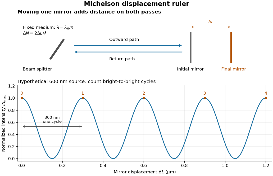
Mirror displacement, doubled optical path difference, and counted interference fringes for a hypothetical Michelson interferometer
. Details. 
For an original hypothetical example, suppose in the actual surrounding medium and a continuous scan gives cycles, including the final fractional cycle. Then . With the wavelength treated as exact, a fringe-reading measurement uncertainty of cycle contributes to the displacement measurement uncertainty. An uncertainty of in a local phase difference instead corresponds to . This illustrates measurement resolution, not a complete claim of accuracy: wavelength calibration, air changes, mirror tilt and missed cycles can dominate.
To separate the oscillating readout from its optical coherence envelope, use the local modelHere is detected light intensity, is the mean level, is a fixed bias wave phase, and is interferometric visibility. A fine scan of measures the carrier phase difference; a coarse scan can map the temporal optical coherence envelope through . The envelope maximum locates matched delays only under the source and apparatus assumptions; it is not a bright fringe identifying an arbitrary mirror position. Even with known , one intensity reading leaves the cosine sign and whole-cycle ambiguities. Continuous motion of known direction, or an independently obtained pair of signals in phase quadrature, is needed to recover signed travel through reversals.
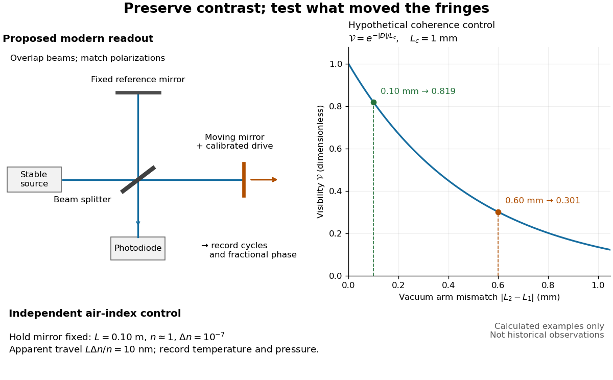
Proposed Michelson interferometer readout and hypothetical optical coherence and refractive index controls
. Details. 
The figure's original control example stipulates equal arm light intensities, matching linear polarizations, and a Lorentzian optical spectrum giving with . In vacuum, arm mismatches and give and . Matching the arms improves the phase difference readout without changing its travel per cycle. A fine mirror scan of one cycle changes by only for the stipulated source, much less than . These are calculated values, not historical data.
A proposed measurement sequence follows from this model. Overlap the returning beams, match their linear polarizations, find a high-contrast delay and use a small calibrated mirror scan to determine the sign and fringe period. Read a fixed spatial sample of the interference fringes with a photodiode; record each arm separately and the dark signal, avoid detector saturation, and retain enough time resolution to count every cycle. Approach mechanical settings consistently and repeat the return scan to expose lost motion or drift. For very small changes, bias near phase quadrature, where is largest; an intensity extremum has zero first-order sensitivity. A known drive voltage alone does not provide measurement calibration for mirror travel: compare the actual travel with the fringe count using an independently known wavelength.
Control temperature, pressure, vibration and air currents because the instrument measures optical path difference, not mirror motion alone. For a fixed reference arm and fixed , the first-order change of the moving arm's round-trip path is . Thus an unrecognized mimics . A hypothetical , , and give apparent travel. Holding the mirror still while varying or monitoring the air conditions tests this confounder. Separate checks of alignment, wavelength stability and thermal expansion are necessary before sub-fringe measurement resolution becomes a defensible measurement uncertainty.
Albert Abraham Michelson's 1907 lecture, Recent Advances in Spectroscopy, pp. 171–172, connects counting interference fringes with a reproducible length standard. Broad or multiple spectral lines obscured fringes at large path differences; red cadmium emission supplied a suitable source. His 1907 Nobel Prize in Physics recognized optical precision instruments and their spectroscopy and metrology applications.[ref]
Recent Advances in Spectroscopy by Albert Abraham Michelson. Nobel Lectures, Physics 1901–1921; Michelson, Nobel lecture, printed pp. 171–172; official prize motivation, printed p. 158
His authored account of the metre comparison at Sèvres describes a heated, evacuated cadmium discharge tube and a spectrometer selecting one spectral line. A movable reference mirror was compared with pairs of silvered parallel surfaces defining intermediate standards. Counted interference fringes established a short interval; repeated comparisons extended it to a decimetre and then a metre. White-light fringes located surface coincidence, while monochromatic fringes supplied counts and fractional orders. A thermally shielding box, firm pier, calibrated translation screw and tested thermometers controlled drafts, vibration, travel and temperature. Uniform temperature mattered in comparisons; the final standard required an absolute temperature reading. Optical microscopes made the final comparison to the marked metre bar, limiting the whole result.[ref]
Lecture V: Light Waves as Standards of Length. Michelson, Light Waves and Their Uses (1903), Lecture V, Figs. 70–77: intermediate standards, counting, temperature controls and final microscope comparison
This is a measurement chain, rather than one enormous unchecked fringe count: short intervals establish whole orders; fractional-order readings refine each longer comparison. The optical coherence envelope helps locate white-light coincidence, whereas the carrier phase difference measures small departures from it. Repetition checks counting mistakes, but agreement alone cannot exclude shared systematic errors. The general lesson of metrology is to preserve the link from the optical ruler through each transfer and control to the final length.
Articles by others on the same topic
There are currently no matching articles.