An ideal operational amplifier has infinite input impedance and open-loop gain, zero output impedance and no offsets or response limits. Its input currents vanish. Stable operational-amplifier negative feedback, a finite output and unsaturated linear operation then imply a virtual short, . Real amplifiers have finite frequency-dependent gain, input bias currents, offset voltage, output loading, finite bandwidth, slew rate and supply-rail limits. Equal input voltages cannot be assumed in an open-loop or saturated circuit.
Here the noninverting input is grounded. In the ideal-feedback limit the inverting node is a virtual ground, so the resistor current charges the feedback capacitor:The initial capacitor charge fixes the integration constant. This is an op amp integrator, with .
A tiny direct-current input, input bias current or offset can drive the output towards saturation. A parallel feedback resistor provides a direct-current return path, giving ; choose over the intended integration band. A reset switch sets initial charge; low-offset components and suitable signal amplitude reduce drift and saturation. The useful band must also remain below the amplifier's bandwidth and slew-rate limits.
For the stipulated finite but constant real gain , infinite input impedance and negligible output impedance, write the inverting-node voltage as . With phasors proportional to ,ThereforeThe low-frequency gain is . The corner is ; above it the amplitude falls as and the phase approaches . phase and describe the same low-frequency inversion. This finite-gain circuit is a low-pass response with an integrating high-frequency regime, not an ideal integrator down to zero frequency. A genuinely frequency-dependent would introduce additional high-frequency limitations beyond this specified model.
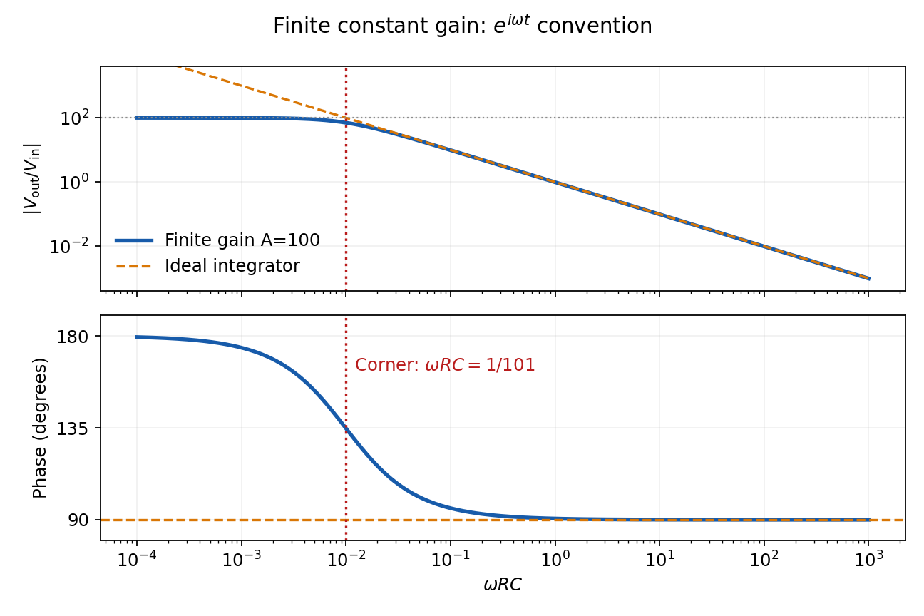
Finite-gain integrator response
. Details. 
Articles by others on the same topic
There are currently no matching articles.