The Fourier expression is the scalar Fraunhofer diffraction approximation for coherent, effectively monochromatic illumination with a uniform incident plane wave over the aperture. At a distant screen the aperture-dependent quadratic propagation phase must be negligible, roughly for transverse size . Alternatively, a thin lens forms the angular Fourier transform in its back focal plane. That focal-plane construction is the appropriate one here; the aperture-to-lens distance need not itself be an enormous free-propagation distance. aperture features should be large compared with wavelength for this simple scalar transmission-mask model.
If complementary transmissions are and , linearity gives . Away from the undiffracted forward beam, the uniform plane-wave contribution vanishes in angular space, so and their intensities agree. This is Babinet's principle. It equates the off-forward diffracted intensities, not the transmitted power or the on-axis intensity including the direct beam.
Let be screen coordinates conjugate to aperture coordinates , so , . With width along and height along , define . The complementary rectangle has transformThus the obstruction's off-forward scattered component hasIts dark lines occur atThe central-lobe zero-to-zero size is by ; it is wider in the direction conjugate to the narrower obstruction. The central forward image of the illuminating beam must be distinguished from this scattered envelope in a real screen observation.
The source figure gives centre-to-centre separation . Choose the three rectangle centres at ; an overall translation changes only the transform phase. Their scattered amplitude is proportional toThereforeAlong the screen's direction, the three-element interference factor has principal maxima separated by , under the single-rectangle envelope. Its zeros lie at and . It also has weaker secondary maxima between principal orders. Every fifth principal order coincides with a single-rectangle zero and is missing; multiplication by the envelope slightly shifts maxima away from the nominal interference-factor positions. The figure plots the calculated scattered component and marks the separate direct-beam limitation.
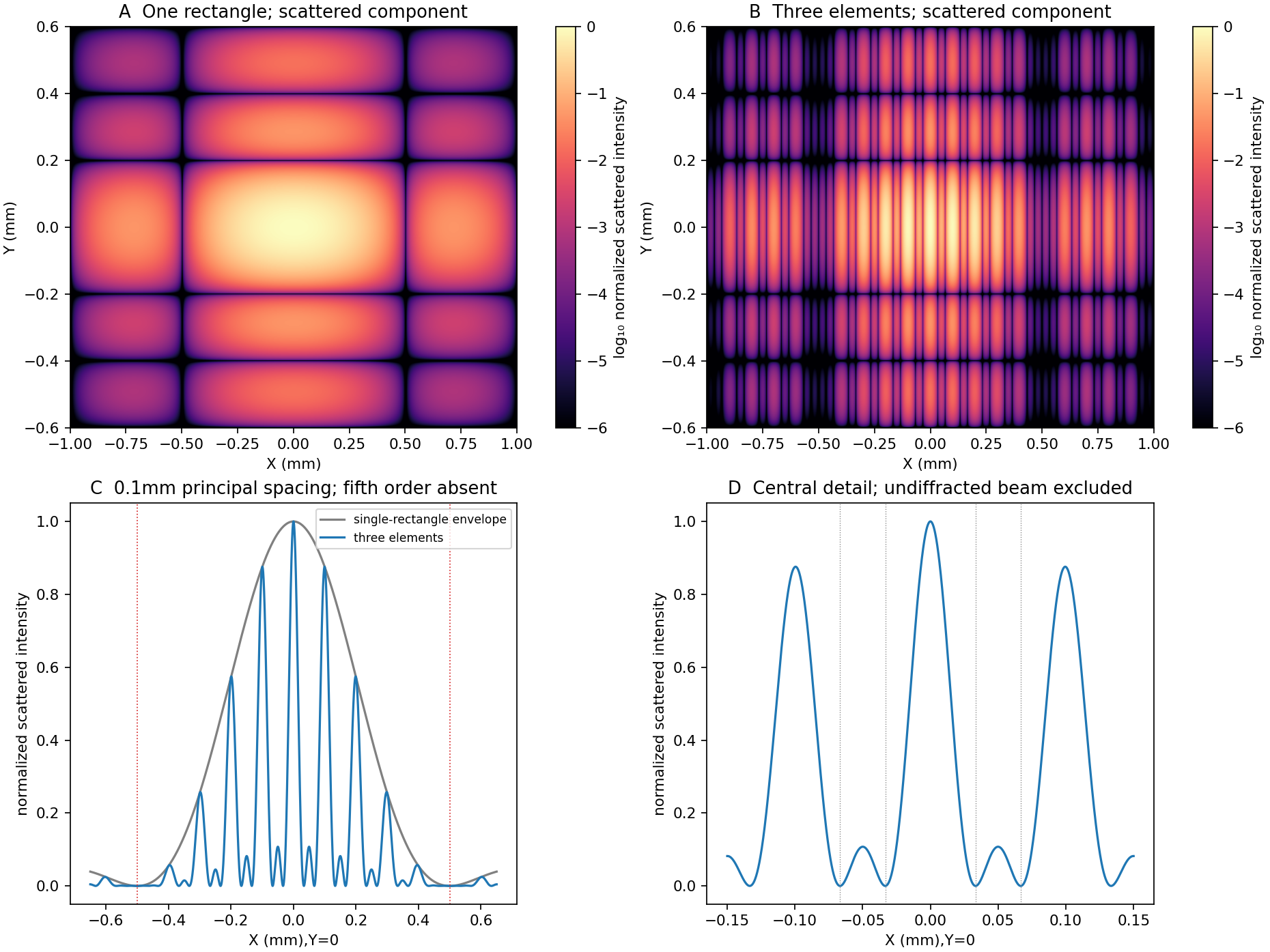
Original calculated rectangular-obstruction and three-element Fraunhofer scattered intensities
. Screen coordinates are physical conjugates of the obstruction coordinates. All plotted values describe the scattered component; the unresolved undiffracted illumination at the origin is excluded. Intensities are normalized, and no source figure is reproduced. Details.
Articles by others on the same topic
There are currently no matching articles.