Use a three-state Moore machine for a rearmable one-cycle pulse generator. Call the states
Ready, Pulse, and Wait. Their outputs are respectively , and initialize in Ready. Labels below are the sampled input pair ab; because simultaneous ones are unspecified, choose reset priority for 11.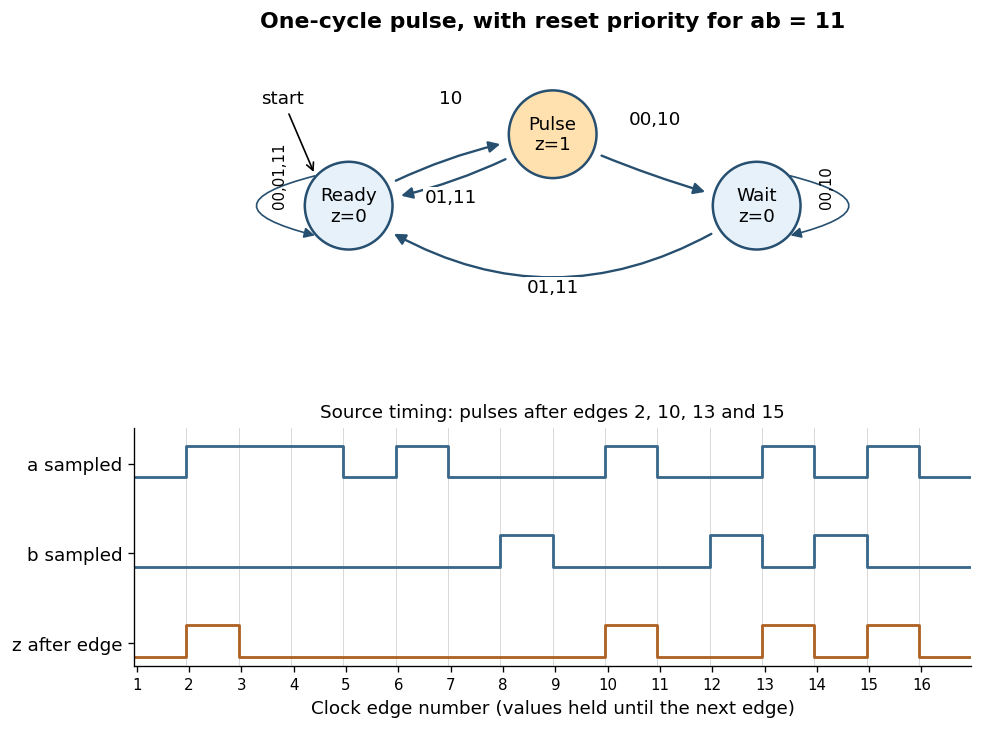
Rearmable one-cycle pulse generator and reproduction of the specified timing behavior
. Details. 
The complete chosen state transition table is
| State | |||||
|---|---|---|---|---|---|
Ready | Ready | Ready | Pulse | Ready | |
Pulse | Wait | Ready | Wait | Ready | |
Wait | Wait | Ready | Wait | Ready |
A sampled trigger
10 causes a pulse only in Ready. Leaving Pulse unconditionally on the next edge keeps its output high for exactly one clock period, even if a remains high. In Wait, further triggers are ignored until a sampled reset rearms the finite-state machine.The crucial transition is
Pulse --01--> Ready. If reset occurs in the cycle immediately following a trigger, this transition both ends the current pulse and rearms the circuit. The next trigger then produces a pulse after just one intervening low-output cycle. Sending every exit from Pulse to Wait would lose that reset and fail the alternate-cycle requirement. This behavior is explicitly visible in the last three pulses of the original timing diagram.[ref]Functional programming, data structures and algorithms, procedural programming, and digital hardware examination paper by the University of Oxford (2003). Printed p. 8, Question 10(b)(iii), last reset and trigger alternations
For the sixteen sampled pairs in that diagram, numbering the first edge as 1,
z is high just after edges and low after every other edge. Equivalently,The two low-output states cannot be merged: the same future trigger must produce a pulse from Ready and be ignored from Wait. A separate high-output state is needed to hold the one-cycle pulse, explaining the three-state design. Articles by others on the same topic
There are currently no matching articles.