An -bit two's complement word represents the integerThe leading bit has negative weight. Words beginning with zero encode the nonnegative values; words beginning with one encode the negative values. Equivalently, interpret the whole word as unsigned and subtract when its leading bit is one. For example, the four-bit words
0111, 1000, and 1111 encode , , and respectively. The range is asymmetric: the most negative value has no positive counterpart in the same number of bits.For a nonzero representable magnitude, complementing all bits and adding one obtains its negative modulo . Fixed-width addition can therefore use the same low-order binary numeral system addition circuitry for signed and unsigned operands; interpreting the result as signed requires detecting integer overflow.
Write and . The operands occupy the integer points of the square . The exact sum is representable precisely whenThe upper boundary is , and the lower boundary is . Within the operand square, the closed band between these lines is representable. The triangle below the lower line has negative overflow, and the triangle above the upper line has positive overflow. The boundary lines themselves are included.
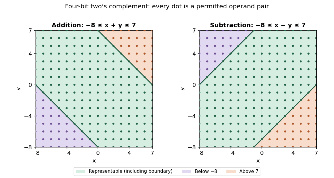

Consequently overflow occurs exactly when or . Negative overflow requires two negative operands; positive overflow requires two nonnegative operands. Same-sign operands alone are not sufficient: their exact sum must cross a range endpoint. Opposite-sign operands never overflow on addition. In terms of the stored wrapped result, addition overflows exactly when the operands have equal sign bits and the result has the opposite sign bit.
The illustration uses , so and , and marks every permissible operand pair. The general region follows from the same two inequalities for arbitrary .
For the exact difference, the representability condition becomesWithin the same operand square , the closed diagonal band between and is representable. Above the upper line, gives negative overflow; below the lower line, gives positive overflow. The right-hand panel of the figure shows these regions, including their representable boundary points.
Positive overflow can occur only when and ; negative overflow can occur only when and . The corresponding exact inequalities are still required: operands with different signs do not always overflow. Same-sign subtraction is always representable. In sign-bit terms, subtraction overflows exactly when the operands have different signs and the wrapped result's sign differs from that of .
One must test subtraction directly or use its correct overflow rule: forming
-y in the same bits fails at , even though some differences with that operand are representable. For example is valid.A D flip-flop stores one bit. On each active clock edge, it samples the input D and changes its stored output Q to that sampled value after the propagation delay. Between active edges, it holds the value. In the ideal discrete model,where is the input sampled at edge and is the state just after that edge. This assumes D meets the required setup time and hold time; asynchronous set or reset inputs, if present, are inactive.
A fully synchronous sequential circuit has all its state stored in edge-triggered elements driven by a common clock signal, with combinational logic computing the next state from the current state and inputs. State updates occur together at the designated clock edges, rather than letting one register output serve as another register's ripple clock. Its ideal equations areFor a Moore machine the output function depends only on the state, . Physical design must leave enough time for register-to-register combinational paths and satisfy setup time and hold time at every receiving storage element.
Use a three-state Moore machine for a rearmable one-cycle pulse generator. Call the states
Ready, Pulse, and Wait. Their outputs are respectively , and initialize in Ready. Labels below are the sampled input pair ab; because simultaneous ones are unspecified, choose reset priority for 11.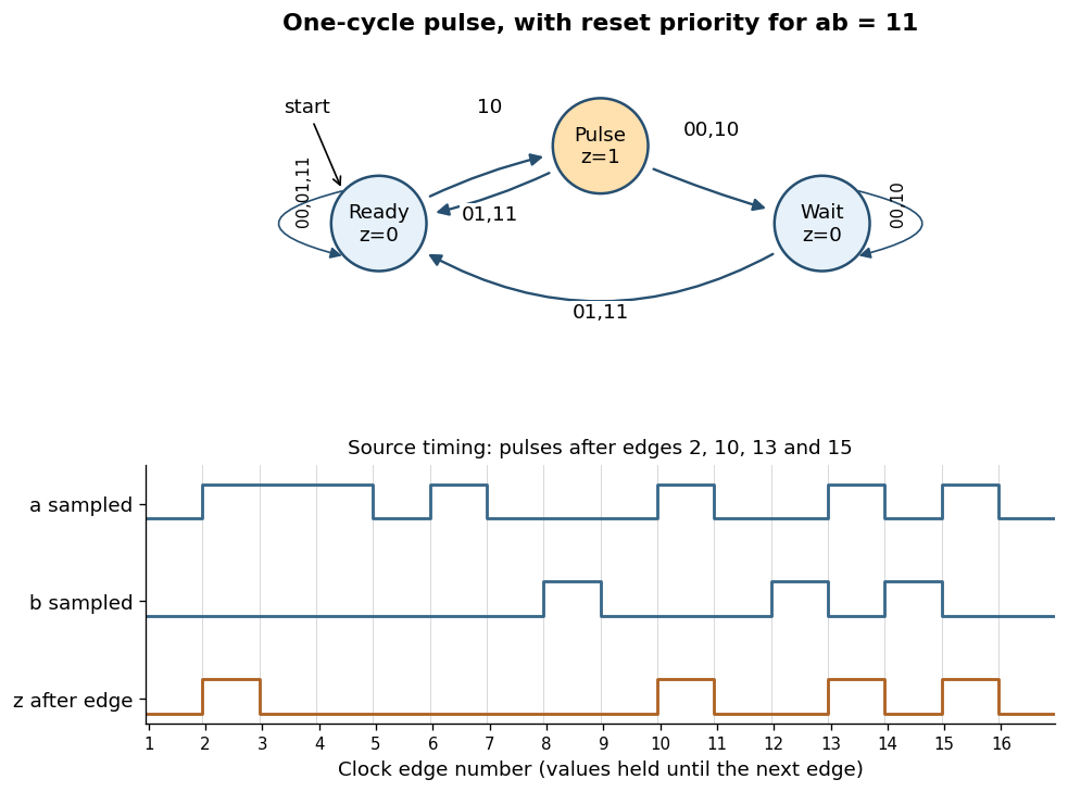
Rearmable one-cycle pulse generator and reproduction of the specified timing behavior
. Details. 
The complete chosen state transition table is
| State | |||||
|---|---|---|---|---|---|
Ready | Ready | Ready | Pulse | Ready | |
Pulse | Wait | Ready | Wait | Ready | |
Wait | Wait | Ready | Wait | Ready |
A sampled trigger
10 causes a pulse only in Ready. Leaving Pulse unconditionally on the next edge keeps its output high for exactly one clock period, even if a remains high. In Wait, further triggers are ignored until a sampled reset rearms the finite-state machine.The crucial transition is
Pulse --01--> Ready. If reset occurs in the cycle immediately following a trigger, this transition both ends the current pulse and rearms the circuit. The next trigger then produces a pulse after just one intervening low-output cycle. Sending every exit from Pulse to Wait would lose that reset and fail the alternate-cycle requirement. This behavior is explicitly visible in the last three pulses of the original timing diagram.[ref]Functional programming, data structures and algorithms, procedural programming, and digital hardware examination paper by the University of Oxford (2003). Printed p. 8, Question 10(b)(iii), last reset and trigger alternations
For the sixteen sampled pairs in that diagram, numbering the first edge as 1,
z is high just after edges and low after every other edge. Equivalently,The two low-output states cannot be merged: the same future trigger must produce a pulse from Ready and be ignored from Wait. A separate high-output state is needed to hold the one-cycle pulse, explaining the three-state design. Articles by others on the same topic
There are currently no matching articles.