Generate four partial-product bits with AND gates:The binary multiplication expansion is . Add the two weight-two bits with a half adder, then add its carry to with a second half adder. The complete combinational logic isThus four AND gates for the partial products and two half adders suffice. Each half adder contains one exclusive or gate and one AND gate. In the largest case , these equations produce , including the necessary fourth output bit.
Split the four-bit unsigned inputs into two-bit halves: and . Use four copies of the two-bit binary multiplier to compute , , , and . ThenThe extreme terms occupy disjoint output positions: uses positions zero to three and uses positions four to seven. Form by concatenating their four-bit outputs, with in the upper half and in the lower half. This needs wiring alone, so without an adder.
Use the first eight-bit adder to form after zero-extension, and the second to form . Thus four two-bit binary multipliers and two eight-bit adders suffice. The fixed left bit shift is also wiring alone.
The middle sum can reach , so preserve all five of its potentially nonzero bits; retaining only four would be wrong. Its shifted value is at most 72. The final result is at most , so both additions fit in eight bits. Concatenating the disjoint extreme terms is what saves an addition.
Use unsigned inputs as in the preceding parts. Store a 16-bit accumulator , a 16-bit shifted multiplicand , an eight-bit multiplier , and a three-bit iteration binary counter . The sequential circuit has one 16-bit adder, a 16-bit multiplexer selecting or zero from , fixed one-place bit shifts, and load/hold selection for the digital registers. The input values are captured when
start is accepted, so later input changes cannot alter the operation.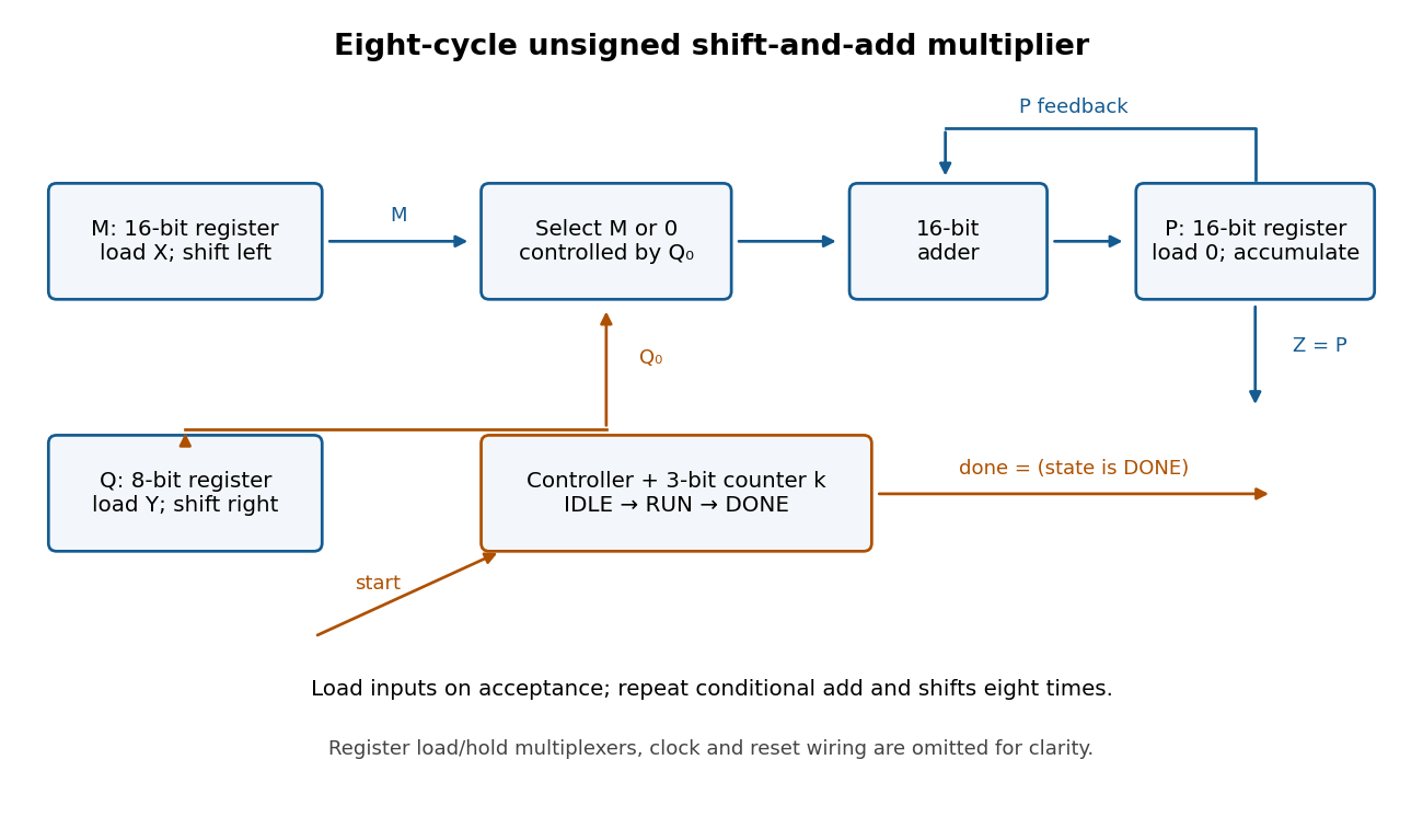

Use three control states with the following synchronous transition table. All assignments in a row use the old digital register values and occur together at the active clock edge.
| State | Condition | Register updates | Next state | IDLE | start = 0 | Hold all digital registers | IDLE | IDLE | start = 1 | , , , | RUN | RUN | , , , | RUN | RUN | , , ; hold | DONE | DONE | start = 1 | Hold all digital registers | DONE | DONE | start = 0 | Hold all digital registers | IDLE |
|---|
Reset selects IDLE and clears the digital registers. Set and
done = 1 exactly in DONE. A start pulse in IDLE launches one multiplication; further pulses during RUN are ignored. Holding start high cannot repeatedly launch operations: DONE waits for it to go low before rearming. The product remains stored while waiting and through the following IDLE state. There are eight RUN clock edges after the loading edge; the last addition is captured before done becomes high.For correctness, let denote the captured values. After iterations, for , the loop invariant isso . Writing , the next accumulation adds , the left bit shift doubles , and the logical right shift changes to . Hence the invariant is preserved. At , , giving . The largest product is , so the accumulator fits. Even the final shifted multiplicand is , so it also fits.
Articles by others on the same topic
There are currently no matching articles.