Source paper: released examination archive, member
2015/T/a10101w1.pdf; original cover dated 2016-06-16. The cover establishes the examination year despite the archive directory name.Use a synchronous binary counter with three positive-edge-triggered D flip-flops, all driven by the same clock signal. Write their outputs , with the least significant bit. The next-state Boolean functions areImplement these with one NOT gate, two exclusive or gates, and one AND gate. Connect each to its corresponding D flip-flop; its output is address line . A reset input clears all three flip-flops to zero, so the first selected sensor is sensor zero.
The state sequence isThe low bit toggles at every clock edge, the middle bit toggles exactly when the old low bit is one, and the high bit toggles exactly when both old lower bits are one. These are precisely the carry conditions for incrementing a three-bit binary representation. Every possible state belongs to the cycle, so there is no unused state requiring recovery. Choose a clock period allowing the combinational logic to settle before the next capture.
For data inputs and selection bits , use a three-to-eight binary decoder. Its output is the minterm that is one exactly when the selection equals the three-bit binary representation of . For example,Gate each data input with its decoded selection using an AND gate, then combine all eight results with an OR gate:Exactly one is asserted, so for the selected , regardless of the other data inputs. A direct implementation uses three shared NOT gates, eight three-input AND gates for the binary decoder, eight two-input AND gates for the data, and one eight-input OR gate. Equivalently, combine each decoder term with its data input in one four-input AND gate. Larger logic gates may be built from two-input ones.
Use eight parallel 8:1 multiplexers and one shared three-bit binary counter. If is bit from sensor , connect to multiplexer . Connect all selection inputs to the binary counter outputs. Then data line carries , so all eight data lines belong to the same selected sensor. Send the three counter outputs to the receiver as the address lines as well.
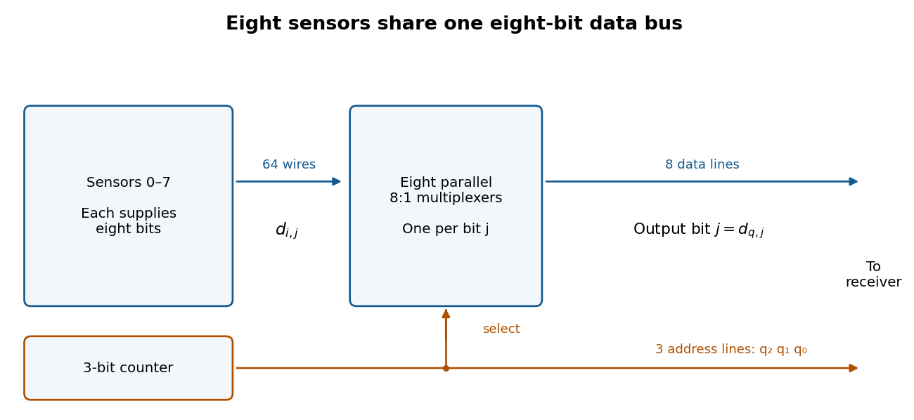
After reset the receiver sees sensors , one per clock period. Sample the data and address only after the binary counter and multiplexers have settled, for example on the opposite clock edge with a sufficiently long clock period. Changing addresses can otherwise cause transient logic hazards. The transmitter uses eleven signal lines, apart from any shared clock or reset connection.
Use an eight-bit modulo-256 binary counter, eight 256:1 multiplexers, eight data lines and eight address lines. Thus there are sixteen signal lines, apart from clock and reset, and a full scan takes 256 clock periods. The counter next-state equations generalize toA 256:1 multiplexer for one data bit can be made hierarchically: 32 first-stage 8:1 multiplexers select within eight-sensor groups using ; four second-stage 8:1 multiplexers select groups using ; one final 4:1 multiplexer selects using . A final 8:1 multiplexer also works if one select input is fixed to zero and only four data inputs are used. Repeat this network eight times, sharing all selection lines. Allow for the extra propagation delay when choosing the clock period.
Generate four partial-product bits with AND gates:The binary multiplication expansion is . Add the two weight-two bits with a half adder, then add its carry to with a second half adder. The complete combinational logic isThus four AND gates for the partial products and two half adders suffice. Each half adder contains one exclusive or gate and one AND gate. In the largest case , these equations produce , including the necessary fourth output bit.
Split the four-bit unsigned inputs into two-bit halves: and . Use four copies of the two-bit binary multiplier to compute , , , and . ThenThe extreme terms occupy disjoint output positions: uses positions zero to three and uses positions four to seven. Form by concatenating their four-bit outputs, with in the upper half and in the lower half. This needs wiring alone, so without an adder.
Use the first eight-bit adder to form after zero-extension, and the second to form . Thus four two-bit binary multipliers and two eight-bit adders suffice. The fixed left bit shift is also wiring alone.
The middle sum can reach , so preserve all five of its potentially nonzero bits; retaining only four would be wrong. Its shifted value is at most 72. The final result is at most , so both additions fit in eight bits. Concatenating the disjoint extreme terms is what saves an addition.
Use unsigned inputs as in the preceding parts. Store a 16-bit accumulator , a 16-bit shifted multiplicand , an eight-bit multiplier , and a three-bit iteration binary counter . The sequential circuit has one 16-bit adder, a 16-bit multiplexer selecting or zero from , fixed one-place bit shifts, and load/hold selection for the digital registers. The input values are captured when
start is accepted, so later input changes cannot alter the operation.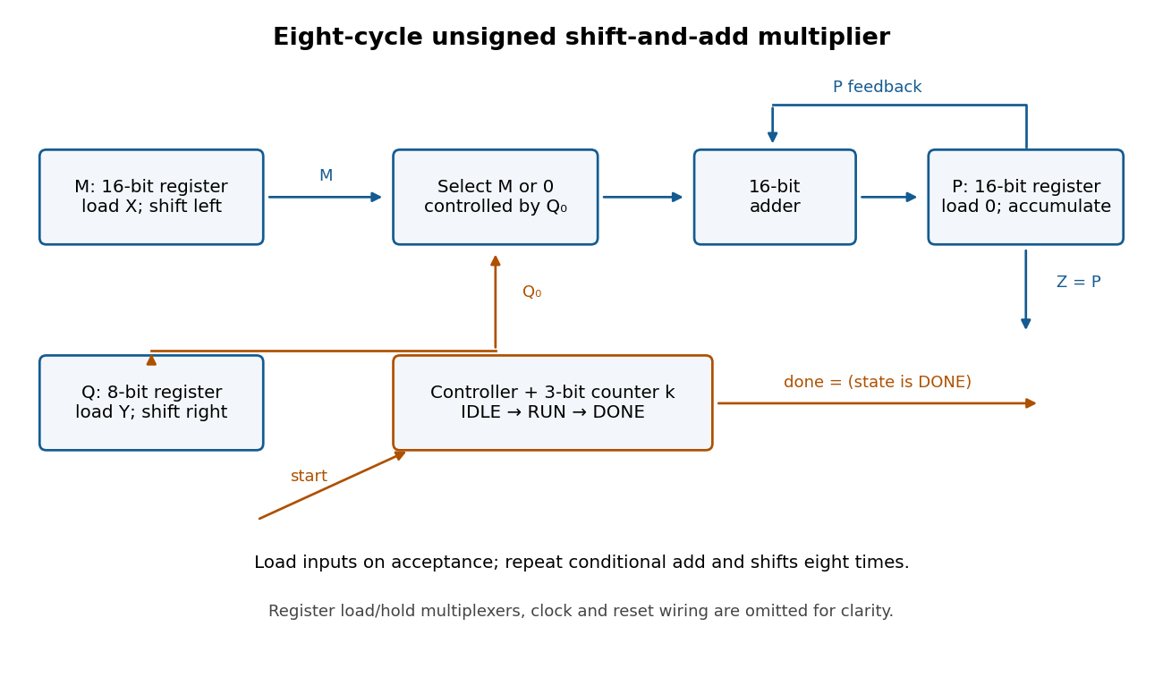


Use three control states with the following synchronous transition table. All assignments in a row use the old digital register values and occur together at the active clock edge.
| State | Condition | Register updates | Next state | IDLE | start = 0 | Hold all digital registers | IDLE | IDLE | start = 1 | , , , | RUN | RUN | , , , | RUN | RUN | , , ; hold | DONE | DONE | start = 1 | Hold all digital registers | DONE | DONE | start = 0 | Hold all digital registers | IDLE |
|---|
Reset selects IDLE and clears the digital registers. Set and
done = 1 exactly in DONE. A start pulse in IDLE launches one multiplication; further pulses during RUN are ignored. Holding start high cannot repeatedly launch operations: DONE waits for it to go low before rearming. The product remains stored while waiting and through the following IDLE state. There are eight RUN clock edges after the loading edge; the last addition is captured before done becomes high.For correctness, let denote the captured values. After iterations, for , the loop invariant isso . Writing , the next accumulation adds , the left bit shift doubles , and the logical right shift changes to . Hence the invariant is preserved. At , , giving . The largest product is , so the accumulator fits. Even the final shifted multiplicand is , so it also fits.
The calling convention passes the integer argument in
$a0, returns the result in $v0, and uses jal with $ra for a call and its return address. The callee returns using jr $ra. Its stack frame grows downwards from $sp and must be removed before returning, restoring the caller's stack pointer.The
$s processor registers are callee-saved registers: a callee that uses $s0 or $s1 must restore their incoming values. The $a, $v, and $t processor registers are caller-saved registers; a caller must preserve any of their values that it needs after a call. Consequently foo keeps its own argument in $s0 and the first call's result in $s1, where nested calls preserve them. Because a nested jal overwrites $ra, foo also saves its incoming return address. Every recursive activation has its own stack frame.The supplied MIPS instructions use the paper's simplified convention: pseudoinstructions such as
subi are accepted, and control transfers have no branch delay slot. The completed code below follows that convention. A hardware implementation with delayed control transfers requires suitable scheduling or nop instructions throughout the supplied code as well.The entry sequence creates one 12-byte stack frame, then preserves the return address and both used callee-saved registers:The closing sequence reverses these effects:Loads must precede deallocation because their offsets refer to the current stack frame. The return value in
subi $sp, $sp, 12    # allocate three four-byte words
sw   $ra, 0($sp)     # save return address of this activation
sw   $s0, 4($sp)     # save caller's s0
sw $s1, 8($sp) # save caller's s1lw $ra, 0($sp) # recover return address of this activation
lw $s0, 4($sp) # restore caller's s0
lw $s1, 8($sp) # restore caller's s1
addi $sp, $sp, 12 # deallocate the frame
jr $ra # return to the caller$v0 is deliberately retained. Saving $ra is essential even though it is not an $s processor register: otherwise the second nested call would destroy the address to which this activation must return.The missing MIPS instructions, in order, areThe comparison
bne  $t0, $0, fooRet1
subi $a0, $s0, 3
add $v0, $s1, $v0slti $t0, $s0, 3 makes $t0 nonzero exactly when , so the first instruction selects the base case. The second forms from the saved argument, rather than relying on $a0 surviving the first call. After the second call, $s1 holds bar(y-2) and $v0 holds bar(y-3); the final addition puts their sum in $v0, as required by the calling convention.The blanks are Although the immediate call increases the argument, substitution into
x < 2 and return x - foo(x + 1). The compiled slti and bne select the first branch exactly for . Otherwise addi forms , jal foo returns its value in $v0, and sub $v0, $s0, $v0 subtracts that value from the preserved . Thus the complete high-level implementation isproc bar(val x : int) : int
begin if x < 2 then
return 1
else
return x - foo(x + 1)
end
endfoo's two recursive calls decreases the corresponding bar arguments to and whenever the recursive branch is entered. The mutual recursion therefore terminates on ordinary integer inputs, assuming sufficient stack space and no machine arithmetic overflow.Keep both the limit and current argument in callee-saved registers, so a call to At every
foo preserves them. Under the same no-delay-slot convention, useli $s0, n
li $s1, 1
slti $t0, $s0, 1
bne $t0, $0, testEnd
testLoop:
move $a0, $s1
jal foo
break 1
beq $s1, $s0, testEnd
addi $s1, $s1, 1
b testLoop
testEnd:
break 0
b testEndbreak 1, $s1 is the tested value and $v0 is its result. Resuming after the breakpoint continues to the next value; after the program reaches its separate final stop. The initial guard handles with no calls. Testing equality before incrementing also avoids overflowing the loop variable after the final call when is the largest positive machine integer. As with the supplied procedures, evaluating all calls assumes enough stack space and representable arithmetic results.The third left-hand side is three times the first minus the second. Consistency of this linear system therefore requires , orThis is also sufficient: the first two rows are linearly independent, and on setting the free variable they giveSubstitution into the third equation gives for either allowed . Explicitly the solution families are and . For every other , the same row relation gives an immediate inconsistency.
Denote the columns by . The first two are linearly independent, because the top two coordinates have determinant . Direct calculation givesThus a column-space basis is , andFor the last description, the third row equals twice the first row plus three times the second, so every column lies in that plane. Since the two independent columns already span a two-dimensional vector subspace, they fill the plane.
The target vector satisfies , so it is in the column space. An especially simple linear combination isIn terms of the displayed basis, the same vector is . The column space itself is unique; the freedom is in choosing its basis.
No. Take the one-by-one matrices , . Both column spaces are , whereas has column space . More generally, taking cancels any nonzero column space. One always has , because each sum column lies in the vector subspace , but equality can fail through cancellation.
For square matrices of the same size,For an upper or lower triangular matrix , its determinant is the product of its diagonal entries:These formulas include singular matrices and zero diagonal entries.
Let be standard coordinate columns. The required elementary matrix isIt is the identity matrix with the extra entry in position . Left matrix multiplication implements the row operation: all other rows are unchanged. Since , is a lower triangular matrix with every diagonal entry one. Part (a) therefore gives andHence adding a multiple of one row to another leaves the determinant unchanged, even if is singular.
Use . The diagonal matrix has diagonal entries equal to , so the product and triangular matrix formulas from part (a) giveEquivalently, multiplying each of the rows by supplies one factor per row.
Write the determinant in its Leibniz formula for determinants, where is the set of permutations of :The permutation sign is justified by the given row-interchange property: a permutation matrix is obtained from the identity matrix by row interchanges, and every interchange changes its determinant by a factor . Reversing a sequence of interchanges constructs the inverse permutation with the same number of interchanges. Consequently . The Leibniz formula for determinants can itself be obtained by expanding the rows multilinearly in the standard basis: repeated selected coordinate rows contribute zero, and the remaining terms are precisely these signed permutation matrices.
Since , the same formula givesReindex the product with and reindex the sum with . Both reindexings are bijections, soThus for every real square matrix, including singular matrices. This proof does not assume the analogous column-operation rules in order to establish the transpose identity.
For a skew-symmetric matrix, . By parts (c) and (d),If is odd, , hence over . Therefore , so is a singular matrix. The conclusion depends on odd dimension: in dimension two, is skew-symmetric and has determinant one.
An eigenvalue and eigenvector pair for a square matrix satisfiesThe scalar and the coordinates of belong to the chosen field, usually or . The nonzero condition is essential: the zero vector satisfies the equation for every and therefore cannot define an eigenvalue.
The vectors are linearly independent ifThey are linearly dependent if some such relation has at least one nonzero coefficient. All coefficients lie in the underlying field. Thus linear independence means that only the trivial linear combination gives zero; linear dependence means that a nontrivial one does.
Apply to the stated linear combination and use each eigenvector equation:Subtract times the original relation. This givesThe assumed linear independence implies separately for every . Since the eigenvector is nonzero, not all can vanish. Choose any with ; division by that coefficient gives . In fact every nonzero coefficient is attached to that same eigenvalue.
Interpret “distinct eigenvalues” as pairwise distinct eigenvalues in the chosen field. Select a nonzero eigenvector for each. A single nonzero vector is linearly independent. Suppose inductively that are linearly independent. If adding made the set linearly dependent, its nontrivial relation would have a nonzero coefficient of , since otherwise it would contradict the induction hypothesis. Solving for would place it in the linear span of the first eigenvectors.
Part (c) would then force for some , contradicting pairwise distinctness. Mathematical induction therefore proves that all selected eigenvectors are linearly independent, forming a basis. If the field is , the assertion requires real eigenvalues; a real matrix can instead have nonreal eigenvalues and a eigenvector basis over the complex numbers.
For , the triangular matrix formula gives the characteristic polynomialThe three eigenvalues are distinct, so part (d) already proves the existence of an eigenvector basis. Explicit choices, ordered by eigenvalues , areTheir column matrix has determinant one, and direct multiplication gives respectively one, three and two times the indicated vector.
For , expansion along the last row givesAgain the three eigenvalues are distinct. An explicit eigenvector basis, ordered by eigenvalues , isIts column matrix has determinant . In particular, 's diagonal entries are not its eigenvalues: it is not a triangular matrix.
Finally , so every nonzero vector is an eigenvector with eigenvalue one. Choose the standard basis . These are linearly independent even though their eigenvalues coincide. Distinct eigenvalues are sufficient for an eigenvector basis, and are not necessary.
The implication introduction rule opens a subproof with a temporary assumption , derives , and discharges that assumption to conclude . The negation introduction rule opens a subproof with a temporary assumption , derives logical falsity , and discharges it to conclude .
The boxes record the scopes and dependencies of the temporary assumptions. A result derived inside a box cannot be used outside it without the appropriate discharge rule; it may depend on the boxed assumption. Other, surrounding assumptions remain in force. This is how the natural deduction rules distinguish a conditional derivation from an unconditional assertion.
Let . In the following natural deduction proofs, indentation and vertical bars mark assumption scopes. Rule names are the introduction and elimination rules supplied by the paper.
First work backwards from the premise using disjunction elimination, proving the whole desired logical conjunction in each case:Alternatively, first transform the goal by conjunction introduction, obtaining and by separate disjunction elimination proofs:The essential difference is the final rule: the first proof splits the premise once, while the second splits the goal first and then analyzes the premise twice. Counting only rule applications, both displayed proofs take nine inference steps. The first uses four conjunction elimination steps, two disjunction introduction steps, two conjunction introduction steps and one disjunction elimination; the second replaces one conjunction introduction with a second disjunction elimination. If assumption lines are counted as displayed proof lines, the second is longer, 14 rather than 12, because it opens four case assumptions rather than two. Thus a raw line count and an inference-step count need not agree.
1  H               premise
 2  | P ∧ Q        assumption
 3  | P            ∧-elim-L 2
 4  | Q            ∧-elim-R 2
 5  | Q ∨ R        ∨-intro-L 4
 6  | P ∧ (Q ∨ R)  ∧-intro 3,5
 7  | P ∧ R        assumption (new case)
 8  | P            ∧-elim-L 7
 9  | R            ∧-elim-R 7
10  | Q ∨ R        ∨-intro-R 9
11  | P ∧ (Q ∨ R)  ∧-intro 8,10
12 P ∧ (Q ∨ R) ∨-elim 1,2–6,7–111 H premise
2 | P ∧ Q assumption
3 | P ∧-elim-L 2
4 | P ∧ R assumption (new case)
5 | P ∧-elim-L 4
6 P ∨-elim 1,2–3,4–5
7 | P ∧ Q assumption
8 | Q ∧-elim-R 7
9 | Q ∨ R ∨-intro-L 8
10 | P ∧ R assumption (new case)
11 | R ∧-elim-R 10
12 | Q ∨ R ∨-intro-R 11
13 Q ∨ R ∨-elim 1,7–9,10–12
14 P ∧ (Q ∨ R) ∧-intro 6,13Proof by contradiction, or reductio ad absurdum, has the formdischarging the assumption . This is the classical rule that concludes directly, as opposed to the negation introduction rule, which concludes a negation.
To derive double-negation elimination using RAA without assuming double-negation elimination itself, useHere line 1 is the negation of line 2. Thus only negation elimination rule inside the subproof, followed by RAA, is needed.
1  ¬¬φ   premise
2  | ¬φ  assumption
3  | ⊥   ¬-elim 2,1
4 φ RAA 2–3Abbreviate and . Use the primitive natural deduction rules, including double-negation elimination:The outer premise is redundant: the proof uses the locally assumed , so the conclusion is already a theorem. Keeping the redundant premise is allowed. The successive discharges give with exactly the requested assumption scopes.
1  H             premise
 2  | H          assumption
 3  | | K        assumption
 4  | | | ¬P     assumption
 5  | | | Q      →-elim 2,4
 6  | | | ¬Q     →-elim 3,4
 7  | | | ⊥      ¬-elim 5,6
 8  | | ¬¬P      ¬-intro 4–7
 9  | | P        ¬¬-elim 8
10  | K → P      →-intro 3–9
11 H → (K → P) →-intro 2–10First derive by double-negation elimination, then derive by negation introduction. The logical falsity elimination rule is used only inside the attempt to derive .Reiteration at line 12 merely uses an assumption that remains in scope. The final follows by conjunction introduction. This explicitly supplies the classical step needed to obtain rather than just .
1  ¬(A → B)  premise
 2  | ¬A     assumption
 3  | | A    assumption
 4  | | ⊥    ¬-elim 3,2
 5  | | B    ⊥-elim 4
 6  | A → B  →-intro 3–5
 7  | ⊥      ¬-elim 6,1
 8  ¬¬A      ¬-intro 2–7
 9  A        ¬¬-elim 8
10  | B      assumption
11  | | A    assumption
12  | | B    reiteration 10
13  | A → B  →-intro 11–12
14  | ⊥      ¬-elim 13,1
15  ¬B       ¬-intro 10–14
16 A ∧ ¬B ∧-intro 9,15Use negation introduction on the unwanted existential quantification, and existential quantifier elimination rule with a fresh witness :The witness name occurs neither in the surrounding assumptions nor in the conclusion of its subproof. This satisfies the eigenvariable condition; it is not an arbitrarily chosen fixed element assumed to witness the existential quantification. The result is .
1  ∀x. ¬P(x)    premise
2  | ∃x. P(x)   assumption
3  | | P(a)     assumption, a fresh
4  | | ¬P(a)    ∀-elim 1
5  | | ⊥        ¬-elim 3,4
6  | ⊥          ∃-elim 2,3–5
7 ¬(∃x. P(x)) ¬-intro 2–6Choose a fresh parameter . The universal quantifier elimination rule supplies both the implication and its premise at that same parameter:The eigenvariable condition holds because is absent from both undischarged assumptions at line 6. Hence the universally quantified implication is proved.
1  ∀x. (P(x) → Q(x))        premise
2  | ∀x. P(x)               assumption
3  | P(a)                   ∀-elim 2
4  | P(a) → Q(a)            ∀-elim 1
5  | Q(a)                   →-elim 4,3
6  | ∀x. Q(x)               ∀-intro 5, a fresh
7  (∀x. P(x)) → (∀x. Q(x))  →-intro 2–6
The proposed version with merely in the antecedent is not derivable. For a counterexample, take a two-element domain with and both true precisely at zero. The universal premise holds. Under the assignment , is true but is false. By soundness, a formal proof cannot exist. Attempting the previous derivation would fail exactly at universal quantifier introduction rule: the parameter would occur in the undischarged assumption , so it would not be fresh.
Write . Use negation introduction on the existential claim. For its fresh witness , instantiate ; the resulting self-application says both and its reverse. The given law of excluded middle then provides the two cases.Both case assumptions are discharged at line 15; the witness assumption is discharged at line 16. Since is absent from the surrounding premise and the exported conclusion , existential quantifier elimination rule is valid. Line 17 is the required negated existential. This is the diagonal self-application underlying the barber paradox.
1  ∀x. ∀y. (S(x,y) ∨ ¬S(x,y))                    premise
 2  | ∃b. H(b)                                   assumption
 3  | | H(b)                                     assumption, b fresh
 4  | | (S(b,b) → ¬S(b,b)) ∧ (¬S(b,b) → S(b,b))  ∀-elim 3, p := b
 5  | | S(b,b) → ¬S(b,b)                         ∧-elim-L 4
 6  | | ¬S(b,b) → S(b,b)                         ∧-elim-R 4
 7  | | ∀y. (S(b,y) ∨ ¬S(b,y))                   ∀-elim 1, x := b
 8  | | S(b,b) ∨ ¬S(b,b)                         ∀-elim 7, y := b
 9  | | | S(b,b)                                 assumption
10  | | | ¬S(b,b)                                →-elim 5,9
11  | | | ⊥                                      ¬-elim 9,10
12  | | | ¬S(b,b)                                assumption (new case)
13  | | | S(b,b)                                 →-elim 6,12
14  | | | ⊥                                      ¬-elim 13,12
15  | | ⊥                                        ∨-elim 8,9–11,12–14
16  | ⊥                                          ∃-elim 2,3–15
17 ¬∃b. H(b) ¬-intro 2–16Equality introduction rule is reflexivity; equality elimination rule permits substitution of equals in a formula:Terms substituted into must be free for substitution, so no variable becomes captured. The notation means substitution into the same designated free variable positions of one formula; other occurrences may remain fixed. These rules express first-order equality without assuming symmetry or transitivity as additional axioms.
For transitivity of first-order equality, take the substitution formula :For symmetry, use reflexivity and :Thus both transitivity and symmetry follow from the two equality rules. In the symmetry proof, only the designated first occurrence in is replaced; the second remains fixed.
1  T₁ = T₂  premise
2  T₂ = T₃  premise
3 T₁ = T₃ =-elim 2,1; φ(u) := (T₁ = u)1 T₁ = T₂ premise
2 T₁ = T₁ =-intro
3 T₂ = T₁ =-elim 1,2; ψ(u) := (u = T₁)Choose distinct fresh parameters . Within the assumption , equality elimination rule gives the forward implication directly. Derive the reverse equality explicitly before using it for the reverse implication:The equality assumption is discharged before either universal quantifier introduction rule. There are then no undischarged assumptions, so both eigenvariable condition requirements hold. The final universal theorem expresses that equal arguments are interchangeable in the predicate in both directions.
1  | a = b                                           assumption
 2  | | P(a)                                         assumption
 3  | | P(b)                                         =-elim 1,2
 4  | P(a) → P(b)                                    →-intro 2–3
 5  | a = a                                          =-intro
 6  | b = a                                          =-elim 1,5; φ(u) := (u = a)
 7  | | P(b)                                         assumption
 8  | | P(a)                                         =-elim 6,7
 9  | P(b) → P(a)                                    →-intro 7–8
10  | (P(a) → P(b)) ∧ (P(b) → P(a))                  ∧-intro 4,9
11  a = b → ((P(a) → P(b)) ∧ (P(b) → P(a)))          →-intro 1–10
12  ∀y. a = y → ((P(a) → P(y)) ∧ (P(y) → P(a)))      ∀-intro 11, b fresh
13 ∀x. ∀y. x = y → ((P(x) → P(y)) ∧ (P(y) → P(x))) ∀-intro 12, a fresh Articles by others on the same topic
There are currently no matching articles.