Use a three-sample run detector. Just before clock edge , let two stored bits and hold the input values at edges and . Initialise both to zero. With input , definePrimes denote the next stored state, with all assignments simultaneous at the clock edge. The output is the logical conjunction of the present input and its two preceding samples. By induction on clock edges, the stated interpretation of is maintained, proving the required behaviour. Two bits of state suffice.
Store two bits: the output , initially zero, and an
armed bit , initially one. Define the synchronous sequential circuit byHere is exclusive or, and the input restriction excludes conflicting commands. The output is the current stored .When armed, a sampled toggles and clears . Further samples leave the output unchanged. A sampled sets without changing , allowing a later to toggle it again. The same clock edge cannot both rearm and trigger because are never simultaneously high. Thus the first toggles from zero to one, and subsequent toggles each require a new followed by a later .
Share the input-history bits of (a) between a high-run detector and a low-run detector. With the two preceding input samples, putThese detector outputs are mutually exclusive. Feed them into (b). An explicit four-bit synchronous sequential circuit, with initial state , isEvery right-hand side uses the old state and the current input. In particular, the run detectors' combinational outputs are sampled by the toggle module at that same edge; there is no extra pipeline stage.
The first three consecutive high samples make at the third edge, toggling and clearing . Continuing high input cannot toggle it again. Only three consecutive low samples can make and rearm it; interrupted low runs do not suffice. After rearming, a new three-sample high run produces the next toggle. This proves the debounced toggle switch behaviour, including rejection of short high and low disturbances.
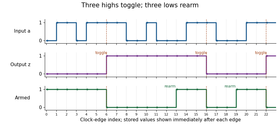
The debounced toggle switch rejects interrupted runs, toggles on the third consecutive high sample, and rearms only on the third consecutive low sample; stored outputs are shown just after each clock edge
. Details. 
Four state bits are necessary and sufficient. For each output value, distinguish three armed situations, remembering a trailing high run of length , and three disarmed situations, remembering a trailing low run of length . Thus a direct minimal behavioural description hasAll twelve situations are reachable. Different output values are immediately distinguishable. Within an armed group, a suitable number of high samples distinguishes the three run lengths by when the next toggle occurs. Within a disarmed group, a suitable number of low samples followed by three highs distinguishes the three rearming distances. An armed situation and a disarmed situation of the same output value are distinguished by an all-high continuation: the armed one eventually toggles and the disarmed one does not. Hence these twelve situations cannot be merged in a finite-state machine implementing the specification.
The shared-history design in (c) uses four bits, meeting this lower bound. Its sixteen encoded states have some behaviourally equivalent histories, so its encoding need not use only twelve combinations. Building two separate copies of (a) plus the two-bit module (b) would use six state-bearing elements; sharing the input history saves two.
Articles by others on the same topic
There are currently no matching articles.