An optical prism is a transparent optical element with nonparallel faces that redirect light by refraction or total internal reflection. For a dispersing prism, the wavelength dependence of refractive index makes different wavelengths leave in different directions.
An entrance slit, collimator, prism and viewing screen or detector form a simple spectroscope. A continuous source gives a spread of colors, whereas a narrow emission line gives a narrow image of the slit. Rotating the prism changes the deviation; replacing the source while holding the geometry fixed distinguishes a source optical spectrum from the prism's dispersive response.
An optical biprism combines two shallow prism regions that deflect parts of an incident beam in different directions. In the familiar Fresnel arrangement, associated with Augustin-Jean Fresnel, the regions act like two thin optical prisms placed base to base. Light from one narrow illuminated slit emerges as if from two separated virtual images of that slit. Where the two parts overlap, their optical coherence permits wave interference.[ref]
User's Manual: Bi-Prism Experiment by Raman Scientific Instruments. PDF pp2–4, apparatus and action of the biprism
This supplies two related optical sources without requiring two independent lamps to maintain a stable phase difference. A bench apparatus uses a narrow slit, the optical biprism, and a movable eyepiece or screen. A micrometer translation measures the spacing of several interference fringes. A convex lens can image the two virtual sources in either of two conjugate positions; if their measured image separations are , their actual full separation is . The inverse magnifications of the two positions explain the geometric mean.[ref]
User's Manual: Bi-Prism Experiment by Raman Scientific Instruments. PDF p2, formula and apparatus; PDF pp4–5, virtual-source interference
A thin-prism calculation makes the geometry explicit. Let each region have small wedge angle , refractive index relative to air, and slit-to-prism distance . The paraxial deviation is . Backward extension of the emergent rays locates the virtual sources a distance above and below the original slit, soAt a screen a further distance beyond the prism, the source-to-screen distance is . Near the axis, the optical path difference is , giving interference fringe spacingThe symbols here use for the full source separation; the apparatus manual uses for that same quantity.
For an original chosen model, , , , and give and . The wedge angle must be converted to radians in the small-angle formula.
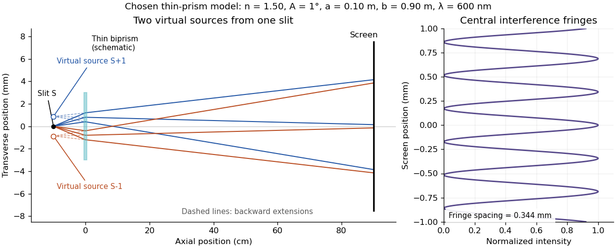
Two virtual sources and the interference fringes of a thin optical biprism
. Original paraxial model with the stated chosen parameters. Solid lines are selected physical rays; dashed lines extend the emergent rays backward to the virtual images. The prism is schematic, and axial and transverse scales differ. The right panel assumes equal coherent amplitudes and shows the central interference fringes, normalized to unit maximum. Details.
A finite slit width, limited optical coherence, unequal beam intensities and misalignment can reduce fringe visibility. The Wollaston prism instead separates linear polarization components using birefringence; its two beams do not automatically interfere on an ordinary intensity screen because their polarizations are orthogonal.
A Wollaston prism, named for William Hyde Wollaston, is a polarizing beam splitter formed from two birefringent optical prisms with crossed crystal-axis orientations. The two linear polarization components encounter different effective refractive indices and leave in different directions. Both output beams are retained, with orthogonal linear polarizations. A manufacturer describes approximately equal and opposite deviations and explicitly defines its splitting angle as the full angle between the emerging beams.[ref]
Wollaston Polarizers by B. Halle Nachfl. GmbH. Opening technical description and full-angle convention
Calcite and quartz implementations illustrate why material matters. The manufacturer uses cemented calcite elements and optically contacted quartz elements; its quartz designs provide smaller splitting angles because the birefringence is smaller. A prism's material, wavelength and cut therefore belong with a stated angular separation, rather than treating that separation as a universal property of the name.[ref]
Wollaston Polarizers by B. Halle Nachfl. GmbH. Opening material discussion and General specifications
The ideal intensity division follows projection onto the prism's polarization axes. For incident linear polarization at angle to one axis and total optical power , a lossless model givesFor an original2milliwatt beam at , the outputs carry1.5and0.5milliwatts. Equal powers occur at45degrees; they are not guaranteed for every input. Unpolarized light gives equal average powers in this ideal model. Real transmission loss and unequal detector responses require separate characterization.
For an original geometric example, suppose a particular prism produces a symmetric full separation . At distance from a common effective exit point, the separation of beam centres isUsing for each beam would mistakenly treat the full splitting angle as a one-sided deviation. Finite beam diameters and any exit-face displacement also affect detector placement.
A bench demonstration rotates a polarizer before the Wollaston prism while recording both output powers. Their complementary variation tests the polarization decomposition. An analyzing polarizer after each exit can check the two output directions independently. Unlike the virtual copies produced by an optical biprism, orthogonally polarized beams have no mutual intensity cross term on a polarization-insensitive screen. Projecting coherent beams onto a common polarization can permit interference after suitable spatial overlap; changing direction alone does not supply that projection.
For the lower-face-first ray path through an equilateral optical prism, take external entry angle , internal refraction angle , base incidence and one total internal reflection at the horizontal base. At the other sloped face the internal incidence equals , so Snell's law gives exit angle again. Its counterclockwise, oriented direction change is the displayed expression with . It is independent of refractive index for this route, but whether the base reflection is total is not. Under normal dispersion, a setting at the green critical threshold sends shorter wavelengths along the total-reflection route while longer wavelengths can leak through the base.
For a homogeneous optical prism in air, let its apex angle be and refractive index . A transmitted ray through both refracting faces exists only iffor a nongrazing symmetric path. At minimum deviation, both internal angles are and both external angles are . Snell's law gives
To see the feasibility condition, the internal angles sum to and each must be below the escape critical angle . The symmetric path satisfies both restrictions exactly when the displayed inequality holds. Under the ordinary transmitted-ray geometry, symmetry also minimizes the sum of the two external angles.
Measuring therefore determines at the chosen wavelength. For and , the deviation is approximately . The formula does not describe an emerging ray when the required refraction is forbidden.
Articles by others on the same topic
There are currently no matching articles.