Birefringence is the existence of different optical propagation constants for different eigenpolarizations in an anisotropic material. It provides the propagation-mode separation needed for adiabatic optical following in a twisted nematic.
Two different refractive indices can produce two displaced images, as in the calcite double-image experiment, or a phase retardation between overlapping components, as in a waveplate. Spatial separation concerns where energy flux travels; phase retardation concerns the relative wave phase. A specimen need not show two visibly separated images to have birefringence.
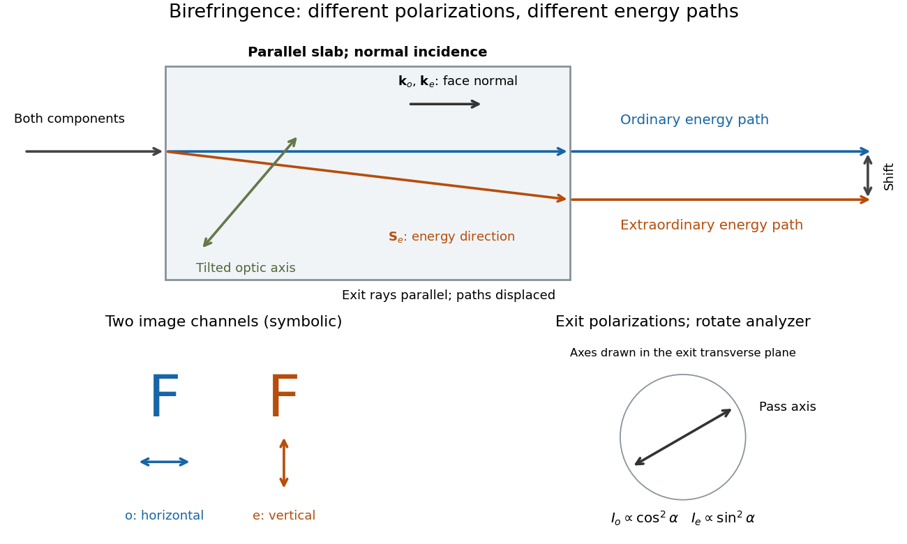
Place a clear calcite specimen on a transparency bearing printed words on an overhead projector. The projected readout is two copies of the lettering. Put a rotatable linear polarizer after the specimen: suitable orientations suppress one copy or the other. These are the actual apparatus and observations in the University of Iowa demonstration.[ref]
Polarization - Calcite & Iceland Spar by University of Iowa, Department of Physics and Astronomy. Demonstration 6H35.15, Equipment and Procedure: crystals, polarizers, printed overhead transparency, two sets of words and selective extinction; final note on natural defects
For a useful control, remove the specimen while keeping the transparency, projector and screen fixed: the doubling should disappear. Replace it, hold it stationary and rotate only the polarizer; complementary brightness changes distinguish two linear polarizations from an accidental duplicate transparency. These are suggested controls, rather than additional reported measurements. Ideally the two copies obey complementary Malus's law curves, and , with angle measured from the exiting ordinary wave's linear polarization. Unequal maxima do not invalidate the test. Finite polarizer extinction, poor focus and specimen defects limit visibility; image separation alone does not determine either refractive index without the specimen geometry.

A transparent, nonmagnetic linear anisotropic dielectric is uniaxial when two principal permittivities agree. With the optic axis along , its permittivity tensor has the displayed diagonal matrix form. Here and are principal refractive indices at a specified frequency; is not the extraordinary wave's index in every direction.[ref]
The symmetry direction of a uniaxial optical medium. For a wavevector along it, the two refractive indices coincide: there is no birefringence for that propagation direction, even though .
The ordinary wave's electric field is perpendicular to the plane containing the wavevector and optic axis. Its refractive index is direction independent at fixed frequency.
The extraordinary wave's electric displacement field lies in that plane and is perpendicular to the wavevector; its electric field need not be. For angle between the wavevector and optic axis,Thus and .[ref]
A short derivation starts from the existing plane wave in an anisotropic dielectric equation. Put and , with angular frequency and vacuum speed of light . The component gives the ordinary wave relation . The determinant of the system givesSubstituting and yields the displayed directional refractive index.
The extraordinary wave's Poynting vector can differ in direction from its wavevector. The latter specifies wave phase propagation, while the former specifies energy flux. This angular separation is walk-off.[ref]
In the lossless, nondispersive model above, take the gradient of to obtain the group velocity, parallel to the Poynting vector. If its angle to the optic axis is , this gives . Consequently the extraordinary wave generally carries energy away from its wavevector direction. An internal wavevector normal to a slab face therefore does not guarantee a normal energy path. Birefringent walk-off vanishes at and ; the latter direction still has unequal refractive indices. This is a useful waveplate geometry: overlapping components can acquire phase retardation without spatial splitting. A thin specimen, insufficient imaging resolution, or excitation of only one linear polarization can also hide a double image, for different reasons.
A waveplate uses birefringence to change polarization of an electromagnetic wave through phase retardation. Its fast axis has the smaller refractive index, hence the larger phase velocity; its slow axis has the larger index. Consider normal incidence with the optic axis in the plate face, so both components follow the same straight path. A linear polarization at to these axes excites equal wave amplitudes.
A complementary experiment uses two sheet polarizers with a cellophane sheet between them. First cross the polarizers and remove the sheet: the field is dark. Insert and rotate the sheet about the beam: light returns at intermediate orientations, but extinction recurs at two perpendicular orientations. The sheet has changed the polarization of an electromagnetic wave, without requiring a resolved double image. With white light, different wavelengths can produce different transmitted colors.[ref]
The Feynman Lectures on Physics, Volume I by Richard Feynman and others. I §33–3, Fig. 33–3 and the paragraphs describing removal, rotation and white-light colors of cellophane
. Brightness alone does not establish circular polarization: an ideal rotating linear polarizer also gives orientation-independent light intensity for unpolarized light.For the overlapping monochromatic wave components, let be the thickness and the vacuum wavelength. Define using the slow and fast refractive indices. With complex amplitude convention , the accumulated slow-minus-fast phase difference isThis is the optical path difference expressed as a wave phase. It is a signed accumulation convention; with the opposite time convention the sign reverses. The outgoing polarization of an electromagnetic wave depends on modulo . Here the positive slow-minus-fast differs from the signed principal-index used in the parent birefringence entry when .
For an original worked example, stipulate at and a uniform thickness . These are design assumptions, not measured material data. The optical path difference is , soIt is a quarter-wave plate. At the same wavelength and refractive indices, doubling to gives , a half-wave plate. A thickness increase changes by , or ; retaining the same birefringence at would instead give for the plate. Real refractive indices also vary with wavelength, so this last calculation explicitly neglects optical dispersion.
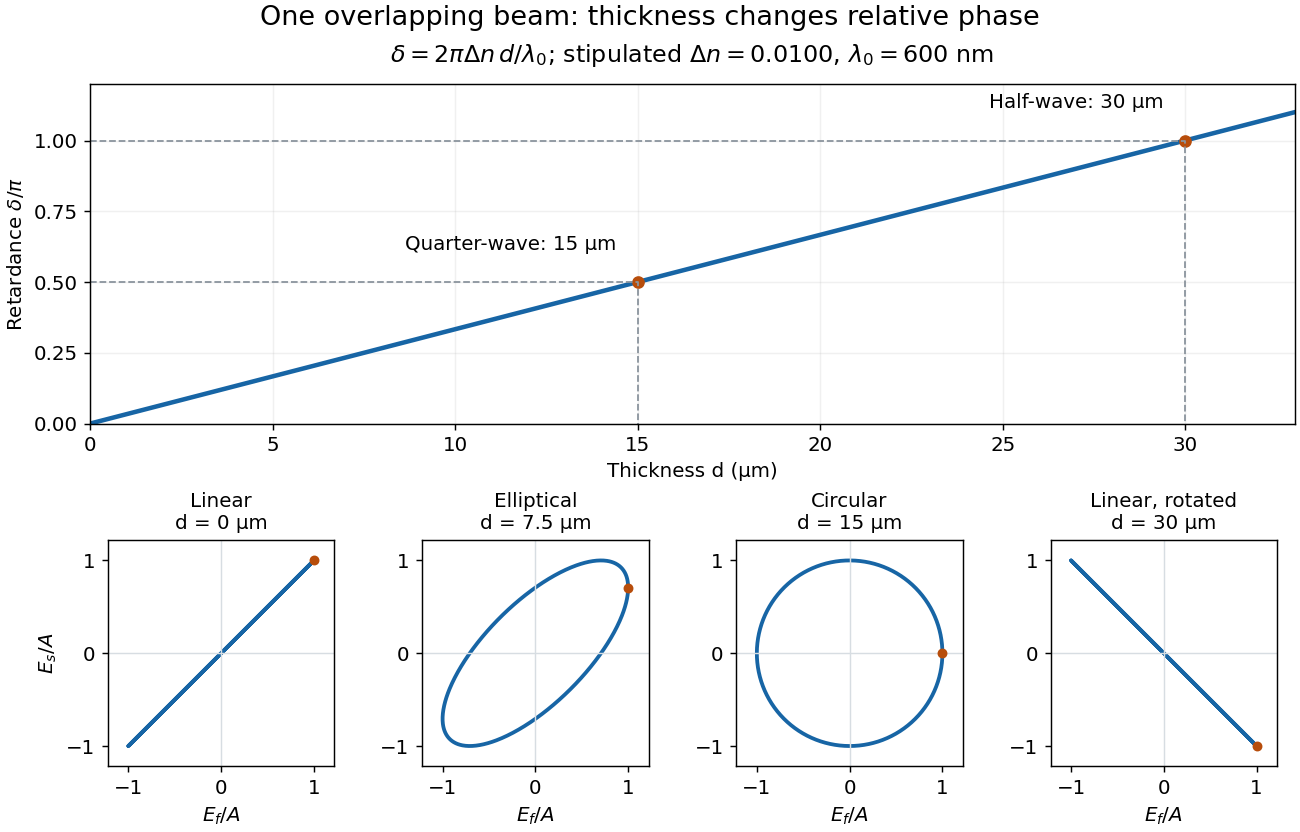
Phase retardation grows with thickness while overlapping components change polarization of an electromagnetic wave
. The stipulated , model gives quarter-wave and half-wave thicknesses of and . Insets trace the normalized electric field at a fixed point for equal fast/slow wave amplitudes, with and . The intermediate ellipse, circle and rotated line require no spatial beam separation. Details.
For these equal transmitted wave amplitudes, orthogonal projection onto a polarizer crossed with the initial linear polarization gives a simple independent readout. After removing a common wave phase, the component complex amplitudes are proportional to ; orthogonal projection onto gives . Squaring its modulus yields : zero at , one half at , and one at . This assumes ideal polarizers, negligible specular reflection and wave absorption, overlapping components and stable relative wave phase. It measures a periodic function of phase retardation, so one brightness measurement cannot determine the thickness uniquely.
A quarter-wave plate gives a quarter-cycle phase retardation. Equal transmitted wave amplitudes initially in linear polarization at become circular polarization; unequal wave amplitudes generally give elliptical polarization. Reversing the sign reverses the traversal of the same circle.
A half-wave plate reverses the relative sign of the two components. For initial linear polarization at angle to the fast axis, the outgoing line is at modulo . The input therefore rotates by .
Articles by others on the same topic
There are currently no matching articles.