The waveguide cutoff frequency separates oscillatory axial propagation from exponential decay for a particular normal mode. For the vacuum-filled rectangular electromagnetic waveguide, the dispersion relation isFor a transverse electric mode of a rectangular waveguide, are nonnegative integers but not both zero. For a mode with and nonzero , both indices must be positive. The lowest cutoff for is consequently , or ordinary frequency .
A square cross-section instead gives equal and cutoffs. The absence of a transverse electromagnetic mode is specific to this hollow pipe, rather than all electromagnetic waveguides.[ref]
Rectangular Waveguide Modes. Haus and Melcher, Electromagnetic Fields and Energy, §13.4, equations (26)–(27) and Fig. 13.4.3: allowed indices, dominant mode and square-guide degeneracy
For , choose real for propagation toward . For , a field decaying into a semi-infinite guide hasA finite section can contain both growing and decaying axial solutions set by its two ends; the single decaying solution is not a complete finite-section transmission calculation. At exact cutoff , the two axial solutions become a constant and a linear function of : there is no finite axial wavelength for a traveling sinusoid.
In the chosen guide at , the branch has . Its amplitude decay length is ; after , its normalized wave amplitude is . This is geometric evanescence even with ideal walls, not Joule heating. A single decaying branch has zero cycle-averaged axial Poynting vector: substituting makes a quarter-cycle out of phase with . Coupling across a finite section requires the complete boundary-value solution.
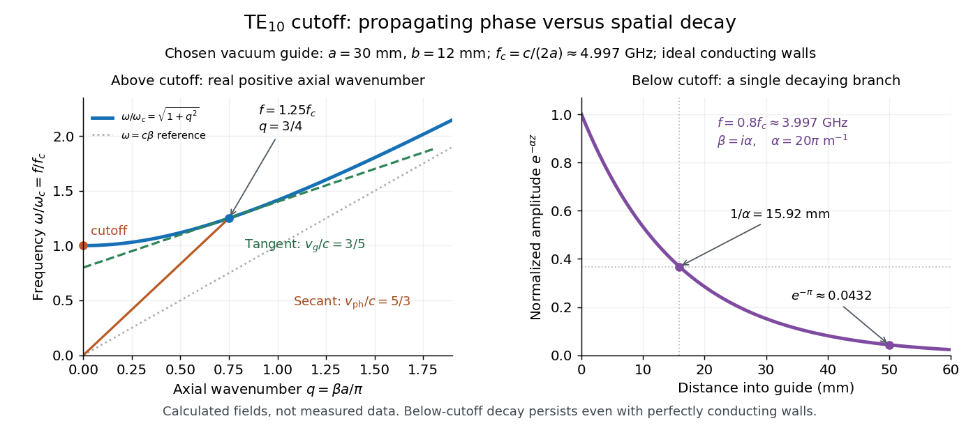

For a propagating branch of an ideal vacuum-filled rectangular electromagnetic waveguide, the phase velocity tracks constant wave phase along the axis, whereas the group velocity describes a sufficiently narrow, weakly distorted wave packet. Using givesThus , , and . Differentiating the dispersion relation proves the second formula; dividing it by proves the first. This is the same mathematical structure as Klein-Gordon packet velocities. In the stipulated example,Over , the corresponding narrow-envelope delay is , approximately . Timing a carrier wave crest would give ; it does not time the arrival of a newly introduced message.
There is an independent energy check. For the forward fields, the average axial Poynting vector is . Integrating across the guide gives average power and average electromagnetic energy per unit length :The transverse sine and cosine squared each integrate to ; then makes the integrated electric and magnetic contributions to equal. The axial energy transport therefore agrees with the group velocity in this ideal model.
As , and ; exactly at cutoff is undefined. Strong wave dispersion close to cutoff also limits the narrow-packet approximation. Neither a large phase velocity nor a pulse peak establishes superluminal information velocity; front velocity asks a separate causal question. In a uniform filling with constant positive permittivity and magnetic permeability , replace by , giving . Frequency-dependent material response or significant loss requires differentiating the actual dispersion relation, so this product is not universal.
Articles by others on the same topic
There are currently no matching articles.