Incoming links: Oscilloscope
AC Josephson effect Updated 2025-07-16
It is called "AC effect" because when we apply a DC voltage, it produces an alternating current on the device.
By looking at the Josephson equations, we see that a positive constant, then just increases linearly without bound.
Wikipedia mentions that this frequency is , so it is very very high, so we are not able to view individual points of the sine curve separately with our instruments.
Also it is likely not going to be very useful for many practical applications in this mode.
An I-V curve can also be seen at: Figure "Electron microscope image of a Josephson junction its I-V curve".
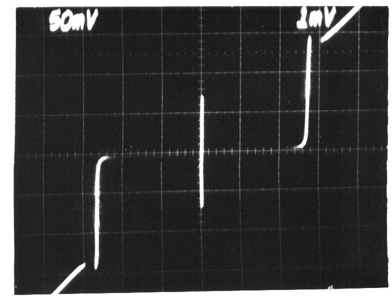
I-V curve of the AC Josephson effect
. Source. Voltage is horizontal, current vertical. The vertical bar in the middle is the effect of interest: the current is going up and down very quickly between , the Josephson current of the device. Because it is too quick for the oscilloscope, we just see a solid vertical bar.
Superconducting Transition of Josephson junction by Christina Wicker (2016)
Source. Amazing video that presumably shows the screen of a digital oscilloscope doing a voltage sweep as temperature is reduced and superconductivity is reached.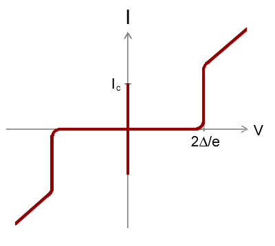
Capacitor Updated 2025-07-16
They can only absorb electrons up to a certain point, but then the pushback becomes too strong, and current stops.
Therefore, they cannot conduct direct current long term.
For alternating current however, things are different, because in alternating current, electrons are just jiggling back and forward a little bit around a center point. So you can send alternating current power across a capacitor.
The key equation that relates Voltage to electric current in the capacitor is:So if a voltage Heavyside step function is applied what happens is:More realistically, one may consider the behavior or the series RC circuit to see what happens without infinities when a capacitor is involved as in the step response of the series RC circuit.
- the capacitor fills up instantly with an infinite current
- the current then stops instantly

Capacitors Explained by The Engineering Mindset
. Source. 2019. Electronic oscillator Updated 2025-07-16
- youtu.be/eYVOdlK15Og?t=66 RC oscillator on breadboard. Produces rectangular wave. Mentions popular integrated circuit that does it: 555 timer IC.
- youtu.be/eYVOdlK15Og?t=175 LC oscillators allows for higher frequencies. Produces sinusoidal output on MHz range. Uses an amplifier to feed back into input and maintain same voltage. Hard to make reliably on breadboard.
- youtu.be/eYVOdlK15Og?t=315 crystal oscillator. Mentions it acts like an LC oscillators. Shows and equivalent model. Wish he had talked more about them. You need support components around it: similarly to the LC case, the amplifier is generally not packaged in.
Fabry-Pérot interferometer Updated 2025-07-16
Fabry Perot Interferometer by JFC UCL (2016)
Source. Description only, reasonable animations. Considers the case of two nearby beam splitters.Fabry-Perot Introduction by Williams College Physics (2020)
Source. Shows a working device. Confocal optical cavity, one of the mirrors scans back and forward moved by a piezoelectric motor, this is called a "scanning Fabry-Perot interferometer".
Does not produce an interference pattern, only an on/off blob, which is then fed into an oscilloscope for analysis. The oscilloscope shows both the mirror displacement (which is given by a voltage) and the light detector output.
LC circuit Updated 2025-07-16
When Ciro Santilli was studying electronics at the University of São Paulo, the courses, which were heavily inspired from the USA 50's were obsessed by this one! Thinking about it, it is kind of a cool thing though.
That Wikipedia page is the epitome of Wikipedia failure to explain things in a way that is of any interest to any learner. Video 1. "Tutorial on LC resonant circuits by w2aew (2012)" is the opposite.
Tutorial on LC resonant circuits by w2aew (2012)
Source. - youtu.be/hqhV50852jA?t=239 series LC circuit on a breadboard driven by an AC source. Shows behaviour on oscilloscope as source frequency is modified. We clearly see voltage going to zero at resonance. This is why thie circuit can be seen as a filter.
- youtu.be/hqhV50852jA?t=489 shows the parallel LC circuit. We clearly see current reaching a maximum on resonance.
Introduction to LC Oscillators by USAF (1974)
Source. - youtu.be/W31CCN_ZF34?t=740 mentions that LC circuit formation is the root cause for Audio feedback with a quick demo. Not very scientific, but cool.
LC circuit by Eugene Khutoryansky (2016)
Source. Exactly what you would expect from an Eugene Khutoryansky video. The key insight is that the inductor resists to changes in current. So when current is zero, it slows down the current. And when current is high, it tries to keep it going, which recharges the other side of the capacitor. Microphone Updated 2025-07-16
Testing and Circuit for a Condenser microphone by RSD Academy (2018)
Source. Not very numerical, but shows a simple working breadboard circuit and an oscilloscope. He whistles with his mouth to get a pretty pure frequency.
That type of microphone requires a bias voltage. The circuit is in Ciro's ASCII art circuit diagram notation:
DC_9---R_10k--+--MICROPHONE--+--G
              |              |
+-------V------+Soundwaves on an oscilloscope by Animated Science (2015)
Source. Dude speaking to microphone. Some analysis of how different sounds look like. No circuit diagram. Sinusoidal Updated 2025-07-16