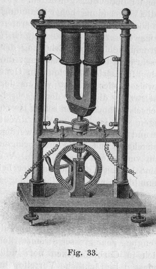
Operated by a hand crank.
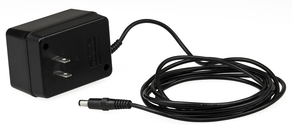
Positive center is way more popular: gearspace.com/board/electronic-music-instruments-and-electronic-music-production/1222518-center-negative-vs-center-positive-power-supply.html


This notation is designed to be relatively easy to write. This is achieved by not drawing ultra complex ASCII art boxes of every component. It would be slightly more readable if we did that, but prioritizing the writer here.
Two wires are only joined if but the following are:
+ is given. E.g. the following two wires are not joined: |
--|--
| |
--+--
|Simple symmetric components:
-,+and|: wireAC: AC source. Parameters:e.g.:If only one side is given, the other is assumed to be at a groundAC_1Hz_2VG.C: capacitorG: ground. Often used together withDC, e.g.:means applying a voltage of 10 V across a 10 Ohm resistor, which would lead to a current of 1 ADC_10---R_10---GL: inductorMICROPHONE. As a multi-letter symmetric component, you can connect the two wires anywhere, e.g.or:---MICROPHONE---| MICROPHONE |SPEAKERR: resistorSQUID: SQUID deviceX: Josephson junction
Asymmetric components have multiple letters indicating different ports. The capital letter indicates the device, and lower case letters the ports. The wires then go into the ports:
D: diodeSample usage in a circuit:a: anode (where electrons can come in from)c: cathode
Can also be used vertically like aany other circuit:--aDc--We can also change the port order, the device is still the same due to capital| a D c |D:--cDa-- | Dac-- | Dca-- | --caDDCDC source. Ports:E.g. a 10 V source with a 10 Ohm resistor would be:p: positiven: negative
If only one side is given, the other is assumed to be at a the ground+---pDC_10_n---+ | | +----R_10------+G. We can also omitpandmin that case and assume thatpis the one used, e.g. the above would be equivalent to:If the voltage is not given, it is assumed to be a variable voltage power supply.DC_10---R_10---GLED: same as diodeI: electric current source. Ports:P: potentiometer source. Ports:1: one of the sides2: the middle3: the other side
T: transistor. The ports aresgTd:Sample usage in a circuit:s: sourceg: gated: gate
All the following are also equivalent:---+ | --sgTd--| g --sTd-- | --Tsgd-- |- ports can also be separated by double underscores from the component names to increase readability. Single underscores can also be used to increase readability of longer multi-word component names e.g.:which is the same as:
RPI_PICO_W__1gp0__3gnd | | R_2k | | | +-aLEDc-+represents a circuit linking port 1 of a Raspberry Pi Pico W, which is GPIO pin 0, through a resistor and an LED, back to pin 3 of the board, which is ground.RPI_PICO_W 1gp0 3gnd | | R_2k | | | +-aLEDc-+
Numbers characterizing components are put just next to each component with an underscore. When there is only one parameter, standard units are assumed, e.g.:means:Micro is denoted as
+-----+
|     |
C_1p  R_2k
|     |
+-----+u.Wires can just freely come in and out of specs of a component, they are then just connected to the component, e.g.:means applying a voltage of 10 V across a 10 Ohm resistor, which would lead to a current of 1 A
DC_10---R_10---GIf a component has more than two parameters, units are used to distinguish them when possible, e.g.:means an AC source with:
AC_1kV_2MHzOpen Circuits book interview by CuriousMarc (2022)
Source. One more more electrical wires surrounded by an insulator.
Main implementations: the same as electronic switches: vacuum tubes in the past, and transistors in the second half of the 20th century.
How to make an LM386 audio amplifier circuit by Afrotechmods (2017)
Source. Builds the circuit on a breadboard from minimal components, including one discrete transistor. Then plays music from phone through headset cables into a speaker.They can only absorb electrons up to a certain point, but then the pushback becomes too strong, and current stops.
Therefore, they cannot conduct direct current long term.
For alternating current however, things are different, because in alternating current, electrons are just jiggling back and forward a little bit around a center point. So you can send alternating current power across a capacitor.
The key equation that relates Voltage to electric current in the capacitor is:So if a voltage Heavyside step function is applied what happens is:More realistically, one may consider the behavior or the series RC circuit to see what happens without infinities when a capacitor is involved as in the step response of the series RC circuit.
- the capacitor fills up instantly with an infinite current
- the current then stops instantly

Capacitors Explained by The Engineering Mindset
. Source. 2019.Pieter van Musschenbroek is the perfect example that if your surname is too complicated, things you invent will not be named after you!


Ideally can be thought of as a one-way ticket gate that only lets electrons go in one direction with zero resistance! Real devices do have imperfections however, so there is some resistance.
First they were made out of vacuum tubes, but later semiconductor diodes were invented and became much more widespread.

Diodes Explained by The Engineering Mindset (2020)
Source. Good video:- youtu.be/Fwj_d3uO5g8?t=153 how it works
- youtu.be/Fwj_d3uO5g8?t=514 applications:
- protection against accidental battery inversion
- rectifiers, notably mentions a diode bridge
The first diodes. These were apparently incredibly unreliable, especially for portable radios, as you had to randomly search for the best contact point you could find in a random polycrystalline material!!
And also quality was highly dependant on where the material was sourced from as that affected the impurities present in the material. Later this was understood to be an issue of doping.
It was so unreliable that vacuum tube diodes overtook them in many applications, even though crystal detectors are actually semiconductor diodes, which eventually won over!
For a long time, before artificial semiconductors kicked in, people just didn't know the underlying physical working principle of these detectors. What I cannot create, I do not understand basically.
They were superseded by transistor radios, which were much more reliable, portable and could amplify the signal received.

How a Crystal radio Works by RimstarOrg
. Source. GPIO generally only supports discrete outputs.
But for some types of hardware, like LEDs and some motors, the system has some inertia, and if you switch on and off fast enough, you get a result similar to having an intermediate voltage.
So with pulse width modulation we can fake analog output from digital output in a good enough manner.
Notably used to connect:
- pin headers
- breadboard holes
You can buy large sets of them in combitation of male/male, male/female, female/female. Male/male is perhaps the most important
These often come pre-soldered on devboards, e.g. and allow for easy access to GPIO pins. E.g. they're present on the Raspberry Pi 2.
Why would someone ever sell a devboard without them pre-soldered!

6x1 pin header
. Source. 
Underside of a Raspberry Pi 2
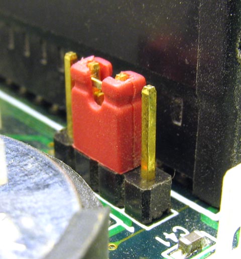
. Source. At the top of this image we can clearly see how the usually pre-soldered pin header connectors go through the PCB and are soldered on both sides.Allows you to connect two adjacent pins of a pin header. Sometimes used as a hardware configuration interface!
- youtu.be/eYVOdlK15Og?t=66 RC oscillator on breadboard. Produces rectangular wave. Mentions popular integrated circuit that does it: 555 timer IC.
- youtu.be/eYVOdlK15Og?t=175 LC oscillators allows for higher frequencies. Produces sinusoidal output on MHz range. Uses an amplifier to feed back into input and maintain same voltage. Hard to make reliably on breadboard.
- youtu.be/eYVOdlK15Og?t=315 crystal oscillator. Mentions it acts like an LC oscillators. Shows and equivalent model. Wish he had talked more about them. You need support components around it: similarly to the LC case, the amplifier is generally not packaged in.
Oscillator made of an LC circuit.
From Raw Crystal to Crystal oscillator
. Source. by United States Army Signal Corps (1943)How LEDs work by VirtualBrain
. Source. 2021. Good 3d schematics clearly explaining part of the LED electronic package.How are LED Chips and LED Encapsulation is made by Future Linear
. Source. Starts from some level of cut square chips. Still in round wafer form.www.reddit.com/r/Optics/comments/18f6bdt/comment/kcsiook/ mentions:
LEDs are broadband by nature, since the spontaneous emission broadly speaking reflects the overlap of the Fermi distribution and the density of states
Bibliography:
It resists to change in electric current. Well seen at: Video "LC circuit by Eugene Khutoryansky (2016)".
Variable resistance element.


Although transistors were revolutionary, it is fun to note that they were just "way cheaper and more reliable and smaller" versions of exactly the main functions that a vacuum tube could achieve
As the name suggests, this is not very sturdy, and was quickly replaced by bipolar junction transistor.
By William Shockley in 1948 also at Bell Labs Murray Hill.


FNIRSI 1014D review by Kerry Wong (2022)
Source. One of the cheapest oscilloscopes available at the time.By Andy Haas, an experimental particle physics professor: as.nyu.edu/content/nyu-as/as/faculty/andy-haas.html What an awesome dude!
They do seem to have been very innovative, and have had a very good work culture. They also had a huge impact on the Silicon Valley startup scene.
Some products they are known for:
- oscilloscopes
- Atomic clocks, notably highly portable ones, see e.g. Video "Inside the HP 5061A Cesium Clock by CuriousMarc (2020)"
- pocket calculator
Articles were limited to the first 100 out of 161 total. Click here to view all children of Electronics.
Articles by others on the same topic
There are currently no matching articles.