Simply supported beam
ID: simply-supported-beam

A simply supported beam is prevented from moving transversely at its two supports while its ends remain free to rotate. In the small-deflection Euler-Bernoulli beam equation, a uniform span with transverse displacement and positive beam flexural rigidity has the support boundary conditionsHere is Young's modulus and is the second moment of area about the bending axis. The second pair expresses zero applied endpoint bending moment, since in the convention used here. It does not set the endpoint beam cross-section rotation or slope to 0. A clamped boundary condition instead constrains both displacement and slope.
For an original derivation, apply a downward central point force and take positive downward. Assume small elastic deflections, constant and no axial preload. Symmetry and force balance give an upward reaction at each support. On the left half, the bending moment is , so . Integrate twice, using and the symmetry condition , to obtainThus the midspan compliance of a simply supported beam isThe endpoint slopes are and : they are generally nonzero. This support geometry and central-load formula are used to infer material stiffness from a three-point bending test.[ref]
The moment-free natural boundary condition for a beam also follows from the principle of virtual work. For a central load, the total potential energy is . An admissible virtual displacement satisfies , while its endpoint first derivatives remain free. Two integrations by parts produce the boundary contributionThe terms multiplying vanish because the endpoint displacements are prescribed. Arbitrary endpoint values of then require there. The free end rotation and zero end moment are conjugate parts of the same variational boundary condition.
Clamping both ends changes the central-load deflection to , one quarter of the simply supported value for the same . It introduces endpoint reaction moments; it does not merely rename the same support. The clamped-beam Green function provides the corresponding fourth-order boundary-value solution. The support conditions likewise determine the simply supported beam normal modes, so a static stiffness measurement and a vibration measurement must use the same mechanical support model when they are compared.
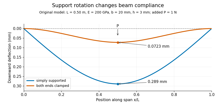
Original central-load beam profiles: allowing support rotation gives four times the midspan deflection of clamping both ends.
Details. 
A three-point bending test places a specimen on two separated supports and applies a central force. A load cell measures force, and a midspan displacement readout measures response. A direct plunger and extensometer can measure specimen deflection separately from machine crosshead displacement, as in the published Instron fixture arrangement.[ref]
Three Point Bend Test Fixtures by Instron. Principle of Operation and midspan deflectometer description
Fitting a proportional small-load segment estimates , where is the measured incremental midspan compliance. Record support spacing, load position and cross-section dimensions with that estimate.For stipulated , rectangular width , thickness and , the second moment of area is and . An incremental central load gives incremental deflection under the simply supported model, versus for the clamped model. Incremental readings remove an unchanged baseline deflection in this linear model; support settling, contact indentation and large rotations require separate interpretation.
New to topics? Read the docs here!