Young's modulus is the ratio of axial stress to axial strain in uniaxial linear elasticity. For an isotropic plate, the bending rigidity is , with thickness and Poisson's ratio .
A tensile modulus experiment asks how much a specimen stretches under an axial force, while allowing its sides to contract freely. For initial cross-sectional area and an extensometer spanning initial gauge length , define engineering stress and engineering strain . In the proportional range,The ratio agrees with this derivative when the line passes through the unloaded origin. A fitted offset should not be mistaken for a material property. Young's modulus has units of pressure: . By contrast, the spring constant of a uniform tensile specimen of length is , with units . Two rods made of the same material can therefore have very different spring constants while sharing Young's modulus.
The normalization removes a useful geometrical ambiguity: doubling doubles the extension at a given force, whereas doubling halves it. For a round specimen ; for a rectangular one , using initial diameter , width and thickness . Diameter error matters twice at first order: . Specify material direction, temperature and loading rate when comparing Young's modulus. Lateral restraint changes the stress state and can prevent this experiment from measuring the uniaxial modulus.
The name commemorates Thomas Young, whose formulation of a measure of elasticity is recorded by the Royal Society. This attribution alone does not establish priority for every modern definition or experimental method.[ref]
Young; Thomas (1773–1829); physician, physicist and Egyptologist by Royal Society. Royal Society person record NA7947, Activity: formulation of a measure of elasticity called Young's Modulus
A flexural modulus is a stiffness inferred from a bending experiment using a specified stress–strain or force–deflection model. It has units of pressure. In a homogeneous, isotropic, linearly elastic slender beam with negligible shear and fixture deformation, it agrees with the Young's modulus entering . It is not the flexural strength or the load at fracture.
For a simply supported uniform beam in a symmetric four-point flexural test, let outer span be , loading contacts lie at and , and be their total force. Integration of the small-deflection Euler-Bernoulli beam equation gives midpoint deflection magnitudeEquivalently, with measured linear slope ,The formula uses midpoint displacement relative to the supports, not automatically the testing machine's crosshead displacement. The underlying moment-curvature law is the beam relation derived by Roylance; actual test conversion additionally requires the fixture spans and specimen geometry.[ref][ref]
For an original rectangular example, choose , , and , so . A corrected midpoint slope gives . This is an inferred model value from stipulated inputs, not a tabulated property of a named material.
If measured displacement includes an extra compliance , the measured compliance is . Ignoring positive fixture compliance reduces the apparent inferred modulus. Transverse shear, anisotropy, nonlinear response and time-dependent material behavior can also make flexural and tensile measurements differ. A reported value should therefore identify geometry, slope convention, displacement measurement and loading conditions.
A chord modulus is the slope of the line connecting two specified points on a stress-strain curve:Instron's glossary defines the calculation by selecting a starting strain and an ending strain and taking the slope between their curve points.[ref]
Modulus of Elasticity in the Instron glossary. Calculating Different Types of Modulus, Chord Modulus
Report the endpoints and strain definition with the value. A linear regression through every observation between them is generally a different estimator.For an original branch , subtraction and factorization giveWith , , and , the endpoint stresses are and , so . The secant modulus from the unloaded origin to the second point is instead . For this quadratic branch, the chord happens to equal the tangent modulus at the midpoint strain; this midpoint equality does not hold for every nonlinear curve.
More generally, the fundamental theorem of calculus gives, for a smooth branch,Thus a chord samples the response across a finite interval. Shrinking that interval can approach a tangent modulus, but measurement noise becomes more consequential when divided by a small strain difference.
For engineering stress and local engineering strain measured with an extensometer,An original specimen with and gauge length gives when force changes from to and local extension changes from to . A constant readout offset cancels in each difference when those same physical states are used; scale errors and machine compliance do not generally cancel. Specify temperature, loading direction and history, since a chord across different branches need not describe one material response.
The secant modulus at a specified point of a stress-strain curve is the slope of the line from the declared unloaded origin to that point:It depends on the chosen point when the curve is nonlinear. Mississippi State University's solid-mechanics laboratory material defines it geometrically in this way.[ref]
Secant Modulus in the Mississippi State University Virtual Laboratory for Solid Mechanics. Strength and Stiffness Characteristics, Secant Modulus definition and diagram at pointA
Specify both the strain measure and the origin when reporting a secant modulus.For an original branch , with and ,At , stress is , the secant modulus is and the tangent modulus is . The first slope relates accumulated stress and strain; the second predicts a small further increment. In linear elasticity through the unloaded origin they both equal Young's modulus.
The relation is especially clear for a smooth curve with . The fundamental theorem of calculus givesThus the secant modulus averages the local tangent slopes over that interval. A chord modulus instead joins two specified states, with slope ; its first state need not be the unloaded origin.
For a tensile measurement using initial cross-sectional area and local gauge length , engineering stress and engineering strain givewhere extension is measured from the appropriate unloaded state. An original , , and yields . A local extensometer avoids attributing all machine compliance to specimen extension. Retain the loading history, temperature and target stress or strain: a secant from an arbitrary preload and an unloading slope are different measurements, particularly after plastic deformation.
The tangent modulus is the local slope of a specified uniaxial stress-strain curve:It converts a small additional strain near into the corresponding first-order change of stress. For nonlinear elastic deformation, this slope can vary with the operating point.[ref]
Elastic Modulus in the Princeton Materials and Mechanics glossary. Elastic Modulus entry, final definition and derivative formula
In uniaxial linear elasticity, , so the tangent modulus equals the constant Young's modulus.[ref]Development of Constitutive Equations for Continuum, Beams and Plates by Tomasz Wierzbicki. Lecture4, p4-1, equation4.1; p4-2, uniaxial-tension assumptions
For an original nonlinear branch, stipulateThen . At , the stress is and the tangent modulus is . The secant modulus from the stipulated unloaded origin is instead . The two slopes answer different questions: the secant compares total stress and strain, while the tangent predicts a small further increment.
For , the tangent predicts . The exact change in the chosen polynomial is because the omitted term is . This is a linear approximation whose error decreases quadratically with the increment, not a claim that the nonlinear material obeys Hooke's law globally.
To estimate a tangent modulus experimentally, specify the stress and strain measures, temperature, loading history and loading rate. For engineering stress and engineering strain from a local extensometer,Fit a local window about the chosen operating point and check how the estimate changes with that window. For an original , and local slope , this gives . Differentiation amplifies measurement noise, and crosshead displacement can include machine compliance. Where plastic deformation or history-dependent response occurs, identify the loading branch: its local slope need not equal the unloading slope or an elastic material constant.
A small arc of a rotating thin hoop needs inward force per length . Its circumferential tension supplies this through curvature, giving tension and tensile stress . Hooke's law converts that stress to circumferential strain, which equals fractional radius change. Small strain, a slender cross-section and uniaxial linear elasticity are required; the cross-sectional area cancels at leading order.
MIT's Spring 2004 laboratory assignment Properties of Heat Treated Steel gives a concrete tensile testing protocol. Record transducer channels and calibration factors; measure specimen diameter and length, and the extensometer gauge length with its locking pin inserted. Zero the load cell, pin the threaded grips into their adapters, and attach the extensometer centrally. Apply the specified seating load, record actuator position, then acquire readings every second while moving at about . The handout derives engineering stress from load cell force, engineering strain from extensometer deformation, and Young's modulus by linear regression below the proportional limit; it warns that actuator-derived strain includes apparatus deformation.[ref]
Properties of Heat Treated Steel by Massachusetts Institute of Technology. Laboratory assignment 10, printed pp. 2–3: Procedure for Tension Tests; Calculations
For a modulus-focused measurement, select a load window after seating, hold temperature and loading rate consistent, and record force, local extension and crosshead displacement together. Fit within that window and calculate . Inspect the regression residuals for curvature; repeat at a lower maximum load and include unloading to check elastic deformation. These are diagnostic additions to the cited protocol, whose full test continues through failure. The handout's seating load is specific to its specimens and apparatus, rather than a universal preload.
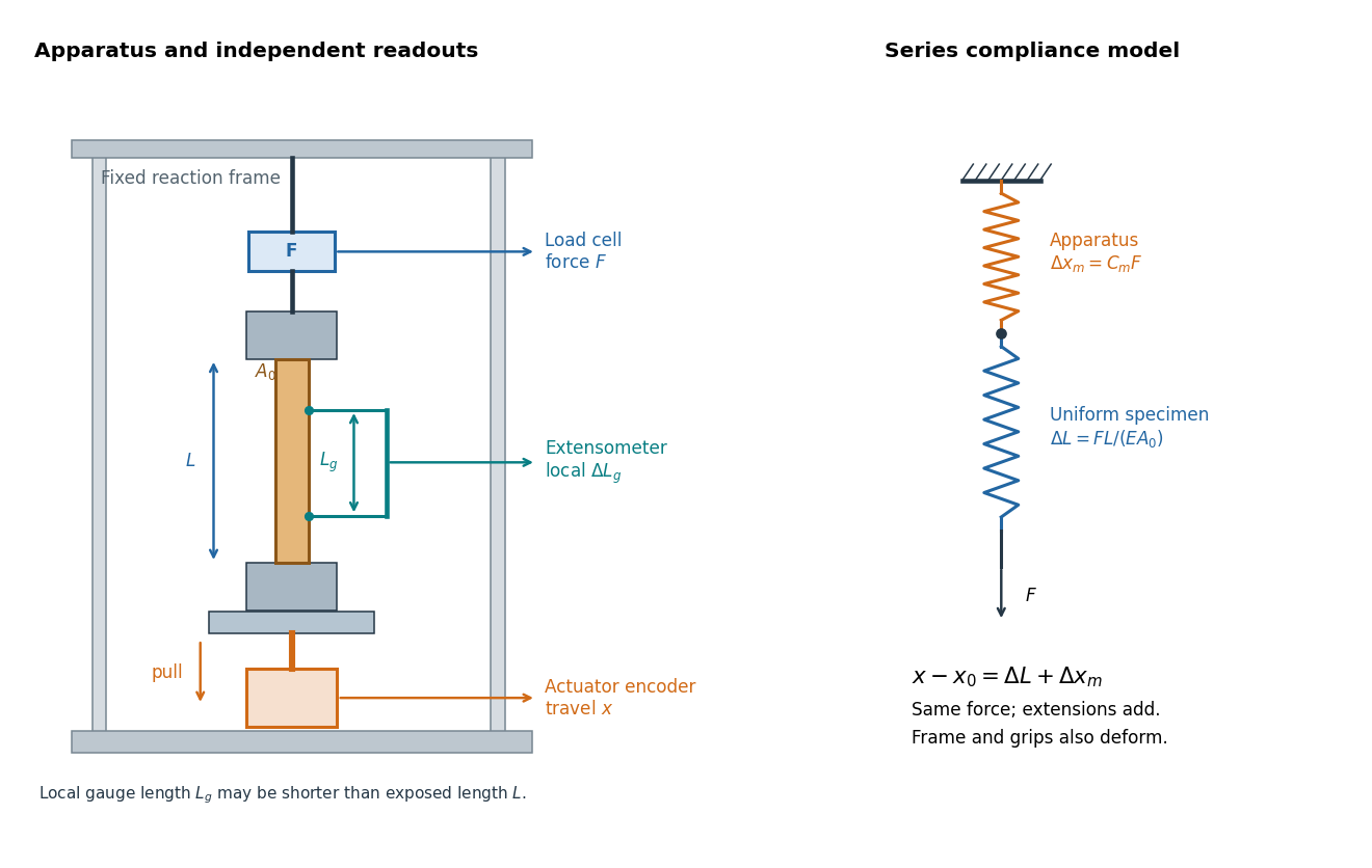
An extensometer measures the change between its contact points; crosshead displacement measures travel of the machine's moving member. The manufacturer Instron explicitly distinguishes local strain from travel that includes machine deformation and machine compliance.[ref]
Static Axial Clip-On Extensometers by Instron. FAQs: How does a clip-on extensometer work?; When should I use a clip-on extensometer instead of crosshead displacement?
The gauge length can be shorter than the uniform length between grips. Thus even a perfectly rigid machine generally has : the local instrument sees only its own segment. Do not divide one channel's extension by the other channel's reference length.Grips must transmit axial force without slip. Misalignment adds bending moment and makes opposite sides experience different axial strains; an instrument on just one side may then report a biased modulus. A changing extension offset, hysteresis between loading and unloading, or load-dependent fitted slope is evidence to investigate seating, slip or material response. A straight line over a short interval alone does not identify which is responsible.
Machine compliance is the extra load-path displacement per applied force attributed to the apparatus in a specified measurement model. Its units are , the reciprocal units of a spring constant. Here includes the frame, load cell, adapters and grips insofar as their deformation contributes to the recorded crosshead displacement . It is a property of that configuration and readout, rather than a universal constant of the testing machine.
Assume a uniform specimen with initial length , constant and Young's modulus , small axial elastic deformation, quasistatic loading, no slip, and a linear, length-independent apparatus response over the chosen force window. Equilibrium makes the same force act through specimen and apparatus, while their extensions add. The two springs in series therefore giveThe offset describes the displacement origin after seating; the slope describes total compliance. Fitting an intercept avoids forcing an arbitrary zero through the origin, but cannot repair slip or a curved response.
If all of is incorrectly attributed to specimen extension, the inferred modulus isFor positive , this is too small. The fractional bias is most serious for a short, thick, stiff specimen because its own compliance is small. A local extensometer instead has in this ideal model, excluding deformation outside its contacts.
A shaped specimen requires more care. With varying initial cross-sectional area and uniform , its axial compliance is in the one-dimensional approximation. Shoulder and end deformation must be included explicitly or remain identical between tests and be absorbed into an effective intercept. Changing only the extensometer gauge length on an unchanged specimen does not change its total compliance and cannot perform a two-length machine compliance separation.
Prepare two uniform specimens with the same material, direction and , but different deforming lengths . Keep grip engagement, adapters, loading window and measurement configuration equivalent. Determine separately by linear regression with its own displacement intercept. Subtracting the two series equations eliminates the common machine compliance:This is an inverse problem: one length supplies only one equation for two unknowns, while two distinct lengths separate the length-dependent specimen contribution from the constant contribution. In a graph of compliance against length, the slope is and the vertical intercept is . It is the compliance, not , that is linear in .
The dimensional analysis is revealing: , so . For , the ideal model requires . A negative fitted challenges the common-intercept assumptions or the measurements. Two lengths determine two parameters exactly, so they cannot test the assumed straight line; three or more lengths allow regression residuals to reveal departures. Nearly equal lengths amplify slope errors through the small difference . If the actual apparatus compliances differ by , the inferred length slope becomes .
The following values are stipulated arithmetic inputs, not measurements of a material. Take and lengths , . At forces , stipulate crosshead displacementsThe two different initial offsets deliberately test the use of intercepts. Linear regression of gives , andTheir reciprocal spring constants are and . The compliance-versus-length slope isso the recovered Young's modulus and machine compliance areThe corresponding apparatus spring constant is .
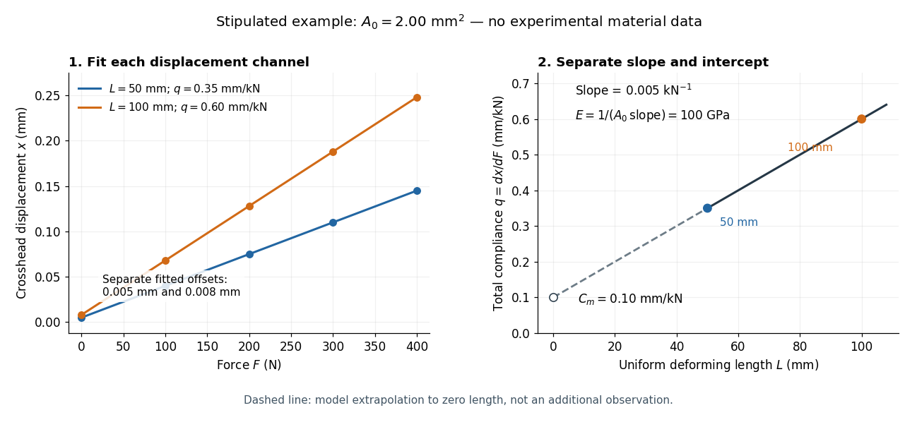
Stipulated displacement fits separate length-dependent compliance from apparatus compliance
. Original calculated example, not experimental material data. Left: independent linear displacement fits at lengths 50 and 100 millimetres retain their different offsets. Right: the line through the two compliance values has slope 1/(EA0) and intercept Cm. The dashed segment extrapolates the model to zero length; it is not a third observation. Details.Check the reconstruction at . The machine contribution is , and the two specimen contributions are and . Adding the respective offsets gives the stipulated and . An extensometer spanning on either ideal uniform specimen would instead read extension: engineering strain , at engineering stress . Their ratio is again . Ignoring machine compliance gives apparent moduli and even after removing the offsets. No yield point or real material identity is implied by these stipulated linear inputs.
Linearity and reversibility answer different questions. The proportional limit ends the interval in which axial stress is proportional to axial strain. Elastic deformation means that deformation is recovered after unloading; a nonlinear response can still be elastic. Conversely, a short straight portion of a loading curve does not by itself demonstrate recovery.
To check recovery, unload and examine the local extensometer strain relative to its initial value, allowing for instrument resolution, drift and any time dependence. A residual extension can indicate plasticity in continuum mechanics, but grip slip can produce a residual in crosshead displacement without the same local residual. Compare the channels before assigning the effect to the specimen. Yield point concerns the onset of irreversible deformation; a specified offset proof stress is an operational convention rather than Young's modulus. For example, a offset proof stress is the intersection of the loading curve with , using the correctly referenced strain. Report the fitted stress/strain window and the unloading evidence alongside the modulus, so that apparatus seating, departure from linearity and onset of plasticity in continuum mechanics remain distinguishable.